


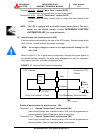
MITSUBISHI ELECTRIC 2033D SERIES UPS
MITSUBISHI
ELECTRIC
2033D SERIES UPS
OWNERS / TECHNICAL MANUAL
Page Number:
2-11
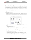
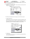
Terminals 33 to 34, 35 to 36 "Minor Fault” contact (OUT8)
Activated when a minor fault has occurred to the system.
Terminals 37 to 38
, 39 to 40 "Total Alarm” contact (OUT9)
Activated when an alarm, a minor fault, or a major fault has occurred to the
system.
NOTE: The UPS is equipped with a selectable output contact feature. The above
alarms are the default settings. Contact MITSUBISHI ELECTRIC
AUTOMATION, INC. for setup information.
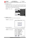
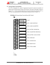
B) Input Contacts (for remote access of UPS)
External contacts are provided by the user of the UPS system. Terminal voltage at the
UPS is 24Vdc. Provide external dry contact accordingly.
NOTE: Do not apply voltages to remote access input terminals. Damage to UPS
may result.
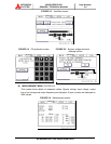
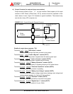
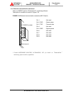
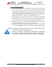
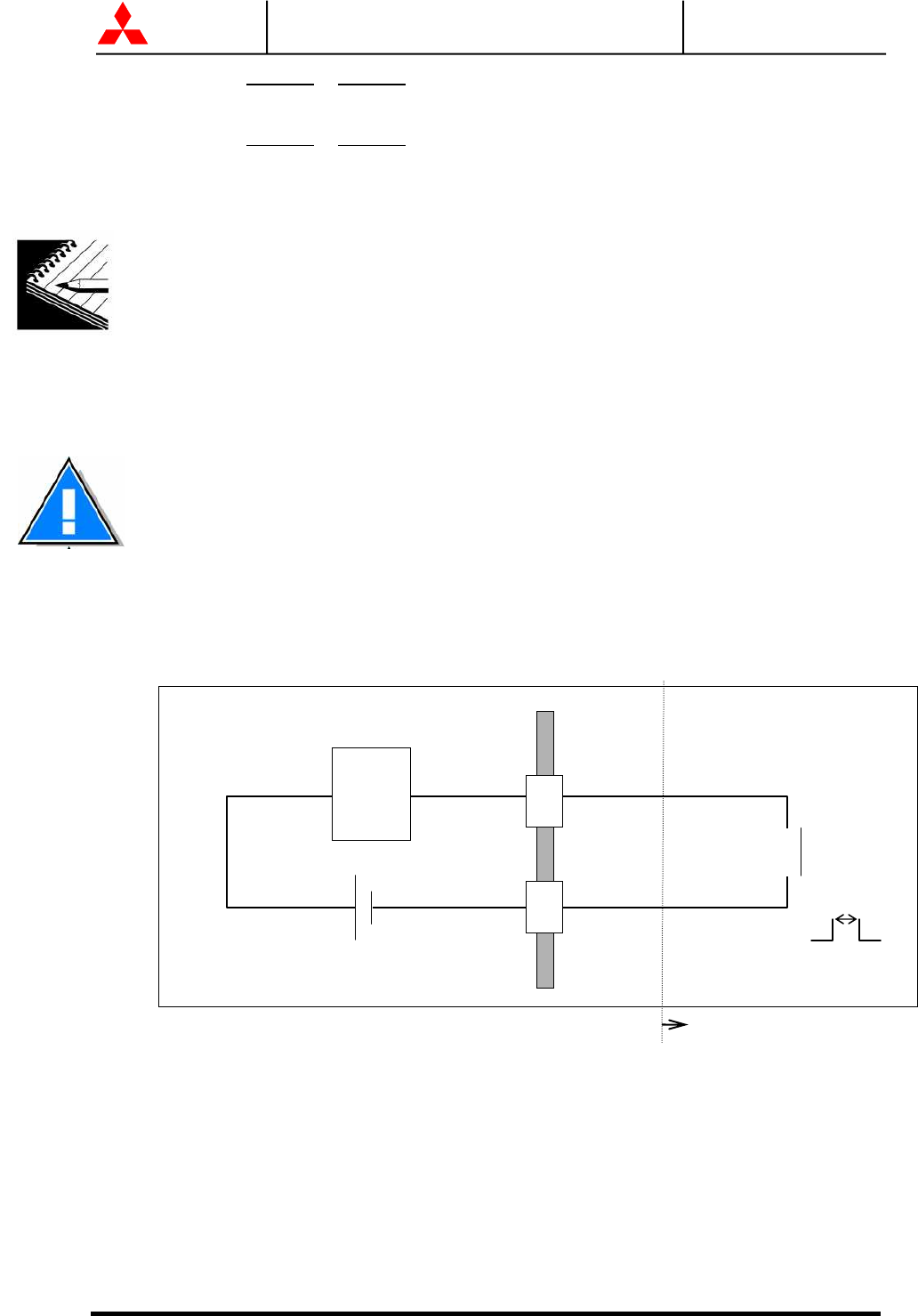
Refer to Figure 2.17 for a typical wiring configuration. Although this figure applies to
the remote start/stop terminals, the same wiring arrangement is used for emergency
stop; battery liquid low; and battery temperature high.
FIGURE 2.17 Remote "Start" Contact Connections
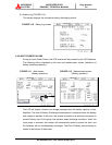
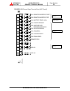
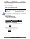
Details of input contacts for remote access : TN2
Terminals 1 to 2 Remote "Inverter Start" input terminal (IN1)
Used to start inverter from a remote location. UPS must be programmed for
remote operation. Refer to Operations Menu for procedure.
Terminals 3 to 4 Remote "Inverter Stop" input terminal (IN2)
Used to stop inverter from a remote location. UPS must be programmed for
remote operation. Refer to Operations Menu for procedure.
Star
t
Rela
y
Coil current : 8.3mA
Use Momentar
y
Switches Onl
y
UPS Cabine
t
External to UPS
Cabine
t
Rela
y
Coil
24 VDC
Star
t
Switch
Common
User supplied
0.5S - 4S
ON
OFF