


MITSUBISHI ELECTRIC 2033D SERIES UPS
MITSUBISHI
ELECTRIC
2033D SERIES UPS
OWNERS / TECHNICAL MANUAL
Page Number:
3
-
3
E) External Battery Supply
Please refer to the following when installing and maintaining batteries:
1. The customer shall refer to the battery manufacturer's installation manual for
battery installation and maintenance instructions.
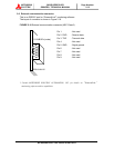
2. The maximum permitted fault current from the remote battery supply, and the
DC voltage rating of the battery supply over-current protective device are
shown in Table 3.4.
TABLE 3.4 Maximum Permitted Fault Current
UPS CAPACITY
(kVA)
DC VOLTAGE
RATING (V)
MAXIMUM PERMITTED
FAULT CURRENT (A)
30 480 25000
50 480 25000
80 480 25000
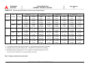
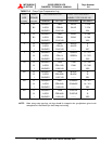
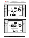
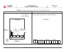
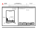
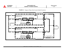
3.3 Procedure for Cable Connections *
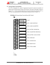
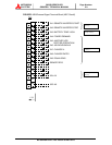
i. Confirm the capacity of the UPS being installed. Identify the input/output power
terminal blocks as shown in the appropriate Figures 3.1-a, b through 3.2-a, b.
ii. Connect the grounding conductor from the input service entrance to the UPS ground bar.
*Wire per local and/or national code.
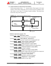
iii. Two (2) sources feeding the UPS
:
(1) Connect the converter input power cables from the input service entrance to the
converter input power terminals, identified as A, B, C in Figures 3.2-a, b. Input
cables must be sized for an ampere rating larger than the maximum input drawn
by the converter. (Refer to equipment nameplate for current ratings.) Refer to
Table 3.5 for recommended cable sizes.
(2) Confirm that an external bypass input circuit breaker (MCCB) is installed (refer to
WARNING 2, page 1-2). Connect the bypass input power cables from the input
service entrance to the bypass input power terminals, identified as A40, B40, and
C40 in Figures 3.2-a, b. Bypass input cables must be sized for an ampere rating
larger than the maximum output current capacity of the UPS. Refer to Table 3.5
for recommended cable sizes.
(3) Referring to Figures 3.2-a, b, connect UPS load terminals A50, B50, C50 and N50
to the load distribution panel. Refer to Table 3.5 for cable sizes.
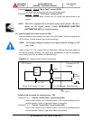
(4) Connect the external signal terminal block as desired. Refer to section 2.5 and Figure
2.15 for functional description. 12 AWG, or less, shielded conductor is recommended.