


MITSUBISHI ELECTRIC 2033D SERIES UPS
MITSUBISHI
ELECTRIC
2033D SERIES UPS
OWNERS / TECHNICAL MANUAL
Page Number:
iv
List of Figures
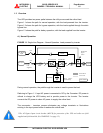
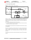
Figure 1.1 Single Line Diagram-Normal Operation .................................................... 1-5
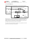
Figure 1.2 Single Line Diagram-Bypass Operation.................................................... 1-6
Figure 1.3 Single Line Diagram-Battery Operation .................................................... 1-7
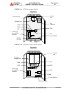
Figure 1.4 UPS Parts Location .................................................................................. 1-8
Figure 1.5 UPS Parts Location (Continued)............................................................... 1-9
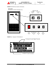
Figure 1.6 External I/F circuit PCB IOAU-05.............................................................. 1-9
Figure 2.1 Operation/Display Panel ........................................................................... 2-1
Figure 2.2 Main Screen ............................................................................................. 2-3
Figure 2.3 Start/Stop Screen ..................................................................................... 2-4
Figure 2.4 PIN Protection Screen .............................................................................. 2-4
Figure 2.5 Bypass Voltage Abnormal Message Screen............................................. 2-4
Figure 2.6 Measurement Screen ............................................................................... 2-4
Figure 2.7 Setup Screen............................................................................................ 2-5
Figure 2.8 Log Select Screen .................................................................................... 2-5
Figure 2.9 Event Log Screen ..................................................................................... 2-5
Figure 2.10 Battery Log Screen ................................................................................. 2-6
Figure 2.11 Main Screen (Battery Operation) ............................................................ 2-6
Figure 2.12 Measurement Screen (Battery Operation) ................................................ 2-6
Figure 2.13 Main Screen (Fault Indication) ................................................................ 2-7
Figure 2.14 Message Screen ..................................................................................... 2-7
Figure 2.15 External Signal Terminal Block................................................................. 2-8
Figure 2.16 Control Wiring for External Contacts ........................................................ 2-10
Figure 2.17 Remote "Start" Contact Connections........................................................ 2-11
Figure 2.18 External communication connector........................................................... 2-13
Figure 3.1 UPS Terminal Designation ...................................................................... 3-7
Figure 3.2 Diagram of input/output bus bars and terminal blocks ............................ 3-8
Figure 3.3 Diagram of Power Wire Connect (Parallel Connection) .......................... 3-10
Figure 3.4 Diagram of Power Wire & Control Wire Connect (Parallel Connection ) . 3-11