Diagnostics 9820/9830/9835 Service Manual
July 1998 TC9830SM Rev. B 7/98 Confidential 21
applies only when you are in Data Dump
mode.
Serial Loop Back Test
This test evaluates serial port circuits on the Control
Board Assembly (nothing external to the Control
Board), so communication setting DIPs 1 through 10
do not affect this test.
TOOLS REQUIRED:
• Loop Back Plug 114271
1. Turn printer off and disconnect host serial port
connector from CN 7.
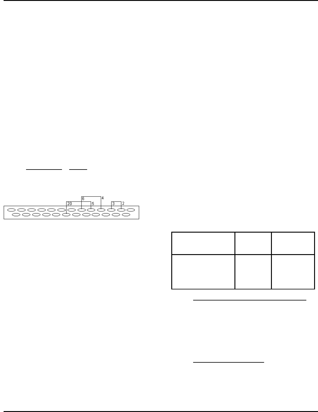
2. Install Loop Back Plug into RS-232 Serial Port
CN 7. See Figure 4-4 for plug wiring.
3. Turn the printer on and go into Diagnostics Test
Mode 2 (002). This is accomplished by pressing
the Feed or Clear key from Mode 1 (001).
4. Press PAUSE.
Jumper Pins Signal
2-3 TXD-RXD
4-6 RTS/DSR
5-20 DTR-CTS
Figure 4- 2. Loop Back Plug Wiring
5. The test runs automatically once initiated, and
takes approximately two seconds.
6. If the test passes, 222 is displayed. If the test
fails (Loopback Plug not installed, installed
incorrectly, or bad Control Board Assy.
components) error #499 is displayed.
7. Press Feed and Clear to exit.
Parallel Port Test
The parallel port timeout test can be used with version
3.1 or greater firmware. When the parallel port is in
flow control, the printer continues to accept data one
character at a time until the entire receive buffer is
full. The rate that data is accepted can be set through
this diagnostic mode. The default is one character per
every 10 seconds. This value prints out on the test
label.
To change the parallel port timeout:
1. Set lower DIP switch 3 to ON. The display reads
000.
2. Press Feed and Clear at the same time until the
display reads 003 (Mode 3).
3. Press Pause to enter the parallel port timeout
mode.
4. Press Clear to increase the timeout and press
Feed to decrease the timeout.
The display changes to show the amount of the
timeout.
5. Press Feed and Clear at the same time to exit
data dump mode. The display reads 000.
The amount of data the application processes from
the communication driver is 128 bytes at a time. Flow
control is now activated when there is 512 bytes left
available in the buffer and flow control is now
deactivated when there is 1024 bytes available in the
receive queue.
Diagnostics Test Mode
There are two types of Diagnostics Tests; those
performed off-line by pressing some keys and those
performed using SENDFILE. Table 4-1 lists the tests
and procedures that can be performed in Diagnostics
Test mode.
Table 4- 1. Diagnostics Tests
DIAGNOSTICS
TEST
OFF-LINE
ONLINE KEYS
Loop Back Test off-line
Pause
Virgin Printer Reset off-line
Feed+Clear+
Pause
Performing a Virgin Printer Reset
A Virgin Printer Reset sets the printer to its original
factory settings and erases all data in RAM. To
initiate a virgin reset, hold down Feed + Clear +
Pause for approximately two seconds, and release.
NOTE: Using “Virgin Reset Command“ in
SENDFILE requires the Service Password.
Printing a Test Label
Print a test label by pressing the Feed while in Data
Dump mode or Diagnostics Test mode. For more
information on printing a test label, see “Test Label,”
earlier in this chapter.
