


Model 926 Knife 9820/9830/9835 Service Manual
Julyl 1998 TC9830SM Rev. B 7/98 Confidential 69
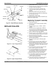
8. Adjust belt tension.
9. Squeeze halfway between pulleys. When
distance from outside of one side of belt to outside
of opposite side is approximately 1.0”, tighten
screws on motor.
10. Turn printer on and test for correct operation.
11. Replace the knife cover.
12. Attach the Stacker Assembly to the Knife
Assembly, see Appendix D.
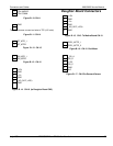
CONNECTORS AND CABLES
The following tables provide pinouts for the Knife
Assembly cables and connectors.
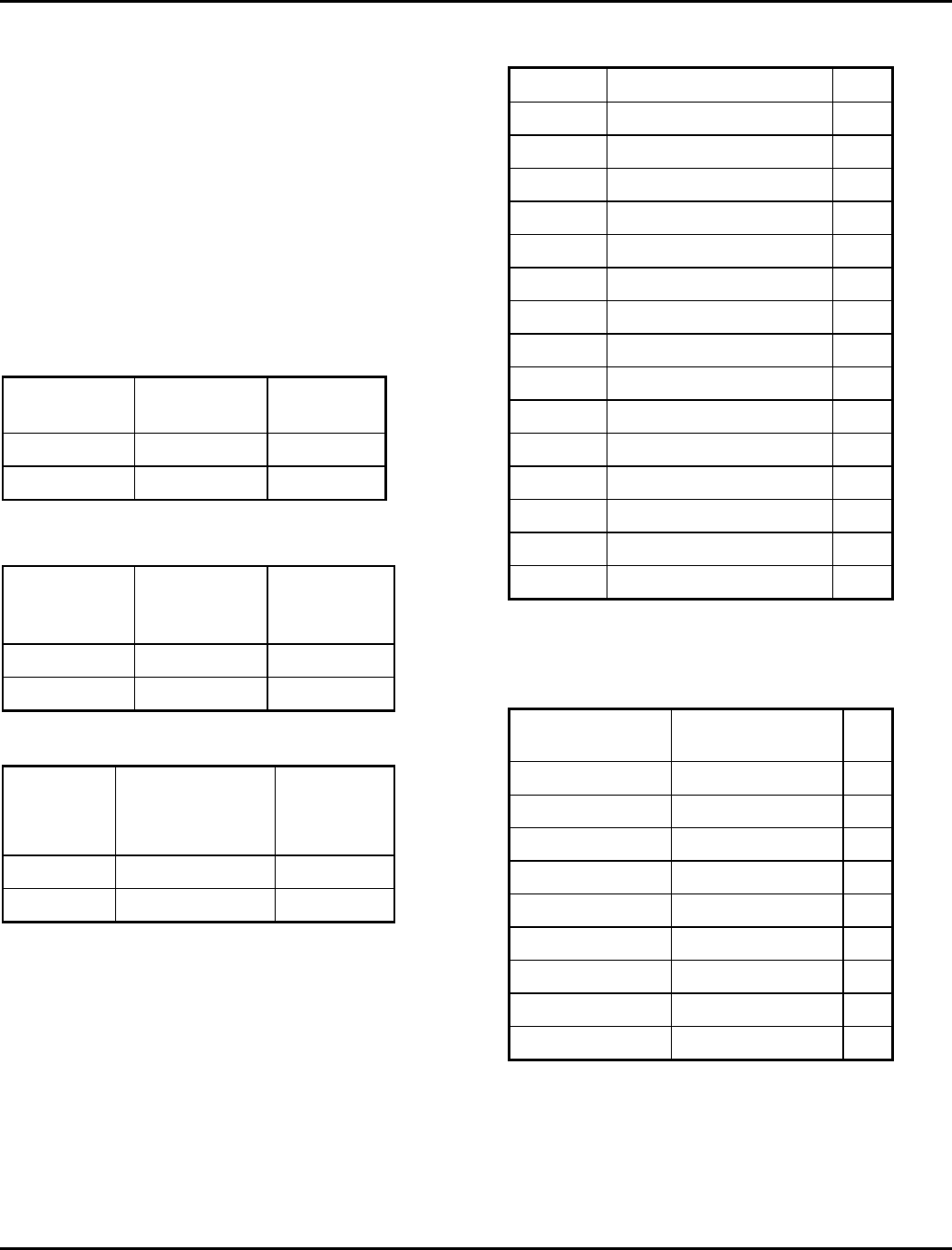
Table E- 2. Drive Board Connector J1.
To Motor
Terminal
Signal Pin
1 25 Vdc 2
2 25 Vdc 2
Table E- 3. Drive Board Connector J2.
To Motor
Solenoid
Terminal
Signal Pin
1 25 Vdc 1
2 GND 2
Table E- 4. Knife Drive Board Connector J3.
From
Printer
CN11 Pin Signal Pin
1 12Vdc 1
12Vdc 2
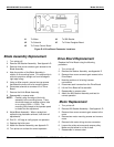
Table E- 5. Drive Board Connector J4 To 928 Stacker
Assembly.
Pin Signal Pin
1 STKR_PRESENT 1
2 STKR_ERROR 2
3 STKR_ENABLE 3
4 +12Vdc 4
5 GND 5
6 GND 6
N/A 7
N/A 8
N/A 9
N/A 10
N/A 11
N/A 12
N/A 13
N/A 14
N/A 15
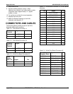
Table E- 6. Knife Drive Board Connector J5.
From Printer
Daughter Board
Signal Pin
CN5 PIN 5 GROUND 1
CN5 PIN 1 STKR_PRESENT 2
CN5 PIN 2 STKR_ERROR 3
CN5 PIN 3 STKR_ENABLE 4
CN4 PIN 6 GROUND 5
CN4 PIN 1 CUT_PRESENT 6
CN4 PIN 3 CUT_ENABLE 7
CN4 Pin 2 CUT_ERROR 8
CN5 PIN 5 CUT_CONTROL 9