


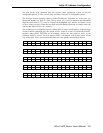
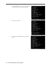
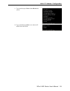

As you use the buttons to operate the LCM display, you will notice that with very few
exceptions, moving up one level causes the bottom line of the display to move to the top line
of the display. You will also notice that the bottom three options in level 2, and all of the
options in level 3 have either a C or D attached.
The meaning is as follows:
• C = configurable
I.e., you are allowed to change the setting of this option
• D = display only
I.e., the setting for this option is displayed, but it cannot be changed (this does NOT
necessarily mean that the number doesn’t change; only that you can’t change it)
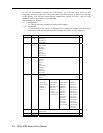
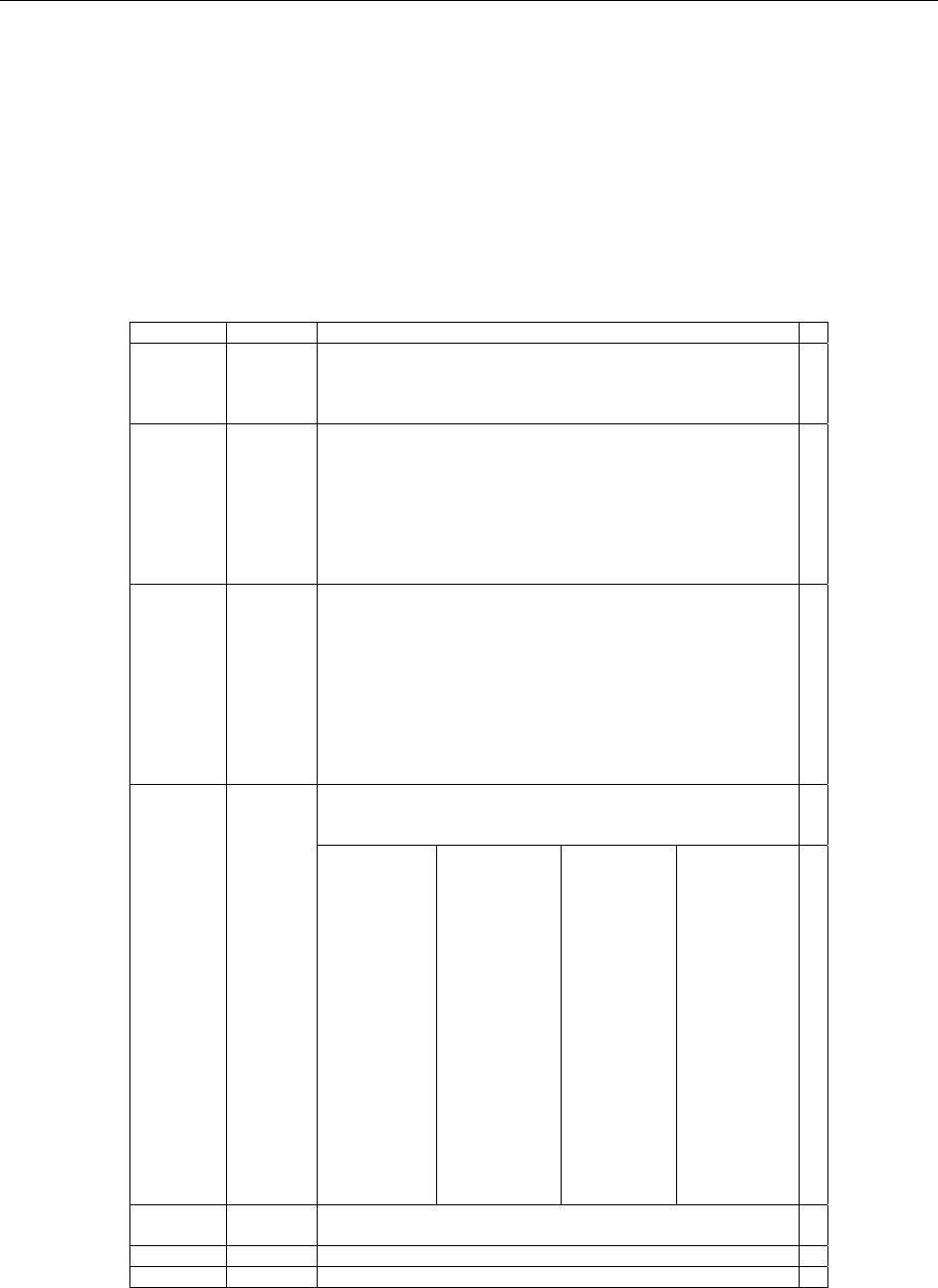
Main Menu
Server
setting
Serial number
Server name
Firmware ver
Model name
D
C
D
D
Network
setting
Ethernet status
MAC address
IP config
IP address
Netmask
Gateway
DNS server 1
DNS server 2
D
D
C
C
C
C
C
C
Serial set Select port
Baud rate
Data bit
Stop bit
Parity
Flow control
Tx/Rx fifo
Interface
Tx/Rx bytes
Line status
C
C
C
C
C
C
C
C
D
D
Select port
Select mode
[mode]
C
C
Op Mode set
Real COM
Alive timeout
Max connection
Delimiter 1
Delimiter 2
Force Tx
TCP server
Alive timeout
Inact. time
Max connection
Delimiter 1
Delimiter 2
Force Tx
Local TCP port
Command port
TCP client
Alive timeout
Inact. time
Delimiter 1
Delimiter 2
Force Tx
Dest IP-1
TCP port-1
Dest IP-2
TCP port-2
Dest IP-3
TCP port-3
Dest IP-4
TCP port-4
TCP connect
UDP svr/cli
Delimiter 1
Delimiter 2
Force Tx
Dest IP start-1
Dest IP end-1
Dest port-1
Dest IP start-2
Dest IP end-2
Dest port-2
Dest IP start-3
Dest IP end-3
Dest port-3
Dest IP start-4
Dest IP end-4
Dest port-4
Local port
C
C
C
C
C
C
C
C
C
C
C
C
C
C
C
C
Console Web console
Telnet console
C
C
Ping C
Save/Restart C
NPort 5400 Series User’s Manual
3-4