


UC-7110 Series User’s Manual Introduction
1-8
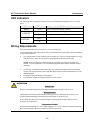
LED Indicators
The following table explains the function of the five LED indicators located on UC-7110’s top
panel.
LED Name LED Color LED Function
Ready Green Power is on and functioning normally.
Green
Serial port 1/2 is transmitting data.
P1/P2 (Tx)
Off
Serial port 1/2 is not transmitting data.
Yellow
Serial port 1/2 is receiving data.
P1/P2 (Rx)
Off
Serial port 1/2 is not receiving data.
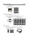
Wiring Requirements
This section describes how to connect UC-7110 to serial devices.
You should heed the following common safety precautions before proceeding with the installation
of any electronic device:
y Use separate paths to route wiring for power and devices. If power wiring and device wiring
paths must cross, make sure the wires are perpendicular at the intersection point.
NOTE: Do not run signal or communication wiring and power wiring in the same wire
conduit. To avoid interference, wires with different signal characteristics should be routed
separately.
y Use the type of signal transmitted through a wire to determine which wires should be kept
separate. The rule of thumb is that wiring that shares similar electrical characteristics can be
bundled together.
y Keep input wiring and output wiring separate.
y It is advisable to label the wiring to all devices in the system.
ATTENTION
Safety First!
Be sure to disconnect the power cord before installing and/or wiring your UC-7110.
Wiring Caution!
Calculate the maximum possible current in each power wire and common wire. Observe all
electrical codes dictating the maximum current allowable for each wire size.
If the current goes above the maximum ratings, the wiring could overheat, causing serious
damage to your equipment.
Temperature Caution!
Be careful when handling UC-7110. When plugged in, UC-7110’s internal components generate
heat, and consequently the outer casing may feel hot to the touch.