


UC-7110 Series User’s Manual Introduction
1-9
Connecting the Power
Connect the “live-wire” end of the 12-48 VDC power adaptor to UC-7110’s terminal block. If the
power is properly supplied, the “Ready” LED will show a solid green color after a 25 to 30 second
delay.
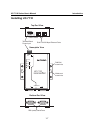
Grounding UC-7110
Grounding and wire routing helps limit the effects of noise due to electromagnetic interference
(EMI). Run the ground wire from the ground screw to the grounding surface prior to connecting
devices.
ATTENTION
This product should be mounted to a well-grounded mounting surface such as a metal panel.
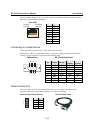
V+V-
SG
12-48V
SG: The Shielded Ground (sometimes called Protected
Ground) contact is the left most contact of the
3-pin power terminal block connector when
viewed from the angle shown here. Connect the
SG wire to an appropriate grounded metal surface.
Connecting Data Transmission Cables
This section describes how to connect UC-7110 to the network, serial devices, and serial COM
terminal.
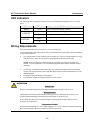
Connecting to the Network
Connect one end of the Ethernet cable to UC-7110’s 10/100M Ethernet port and the other end of
the cable to the Ethernet network. If the cable is properly connected, UC-7110 will indicate a valid
connection to the Ethernet in the following ways:
y The top-right LED on the connector maintains a solid green color when connected to a 100
Mbps Ethernet network.
y The top-left LED on the connector maintains a solid orange color when connected to a 10
Mbps Ethernet network.
y The LEDs will flash when Ethernet packets are being transmitted or received.