


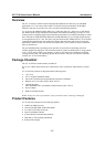

UC-7110 Series User’s Manual Introduction
1-10
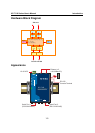
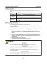
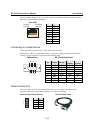
The 10/100 Mbps Ethernet LAN 1 and LAN 2 ports use 8-pin RJ45 connectors. Pinouts for these
ports are given in the following diagram.
8-pin RJ45
1
8
100 Mbps
indicator
10 Mbps
indicator
Pin Signal
1 ETx+
2 ETx-
3 ERx+
4 ---
5 ---
6 ERx-
7 ---
8 ---
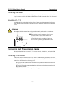
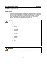
Connecting to a Serial Device
Connect the serial cable between UC-7110 and the serial device(s).
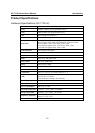
Serial ports P1 and P2 use male DB9 connectors, and can be configured for RS-232/422/485 by
software. The pin assignments are shown in the following table:
DB9 Male Port
RS-232/422/485 Pinouts
12345
6789
Pin RS-232 RS-422
RS-485
(4-wire)
RS-485
(2-wire)
1 DCD TxDA(-) TxDA(-) ---
2 RxD TxDB(+) TxDB(+) ---
3 TxD RxDB(+) RxDB(+) DataB(+)
4 DTR RxDA(-) RxDA(-) DataA(-)
5 GND GND GND GND
6 DSR --- --- ---
7 RTS --- --- ---
8 CTS --- --- ---
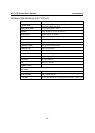
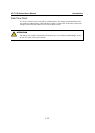
Serial Console Port
The serial console port is a 4-pin pin-header RS-232 port. It is designed for serial console
terminals, which are useful for identifying the UC-7110 boot up message.
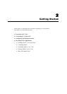
Serial Console Port & Pinouts
Serial Console Cable
4
3
2
1
Pin Signal
1 TxD
2 RxD
3 NC
4 GND