


MRV Communications, Inc. – Installation Manual
9
REMOTE MONITOR
OPTICAL POWER
SYNC
FLAG
AIR RX
LOOP
DO NOT USE
TELESCOPE
TO LIFT UNIT ! !
DS 2
DS 1
FUSION
HEATING
SW MODE
ALIGNMENT
CAUTION
MANAGEMENT
1766240
PS1 PS2 HEATER ON
Rx
3-6
Tx
1-2
Rx
Tx
TELESCOPE
L 3 ON
(BACK VIEW)
LASERS STATUS
L 2 ONL 1 ON
A
VOID EXPOSURE
INVISIBLE LASER RADIATION IS EMITTED FROM THIS APERTURE
AVOID EXPOSURE
INVISIBLE LASER RADIATION IS EMITTED FROM THIS APERTURE
1
1
1010
USE COPPER CONDUCTORS ONLY
TORQUE VALUE 7 Lb-Inch
L
+/~
G
G
N
-/~
HIGH
V
OLT.
LOW VOLT.
POWER
POWER SUPPLY
USE COPPER CONDUCTORS ONLY
TORQUE VALUE 7 Lb-Inch
L
+/~
G
G
N
-/~
HIGH
V
OLT.
LOW VOLT.
POWER
POWER SUPPLY
FOR FUSION
MAIN
TX RX
TX RX
REDUNDANT
F I B E R O P T I C
FLAG FLAG
SYNC SYNC
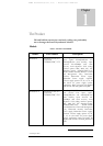
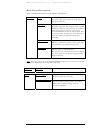
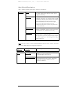
TABLE FOR DS 2
ON
OFF
Normal
-
1,2
Local Loopback
Alignment
1 2
3
3
10
-
8
Mode Select
Remote Loopback
6
6
-
-
Fusion
Window Heater
(if exist)
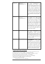
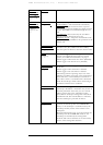
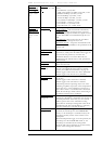
IP Address Setup
Control Mode
Normal
Attenuated
Disable
Enable
Off
On
Default IP
Software IP
HW MODE
SW MODE
Attenuation for
Short Distance Link
-
2
1,2
-
-
10
-
-
5
-
5
-
8
-
1
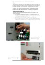
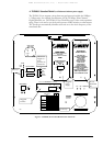
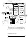
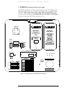
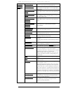
B. TS5000/G-F (Standard Model including Fusion option)
This special TS5000/G-F model can be connected to the back-up radio system
without special MRV’s Switch and card supporting Fusion. This TereScope
can be connected to any Giga-Switch with
1000Base-SX port, which should
be connected to the optical port of the TereScope labeled “Redundant”, while
the back-up radio system is connected to the 10Base-T port of the same
Switch.
For more details please see pages 15 and 16
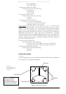
Pluggable
interface, with
Fusion option
Pluggable
Power
Supply
Telescope
DIP Switch
Toggles 4,
7 and 9
positions
are
immaterial.
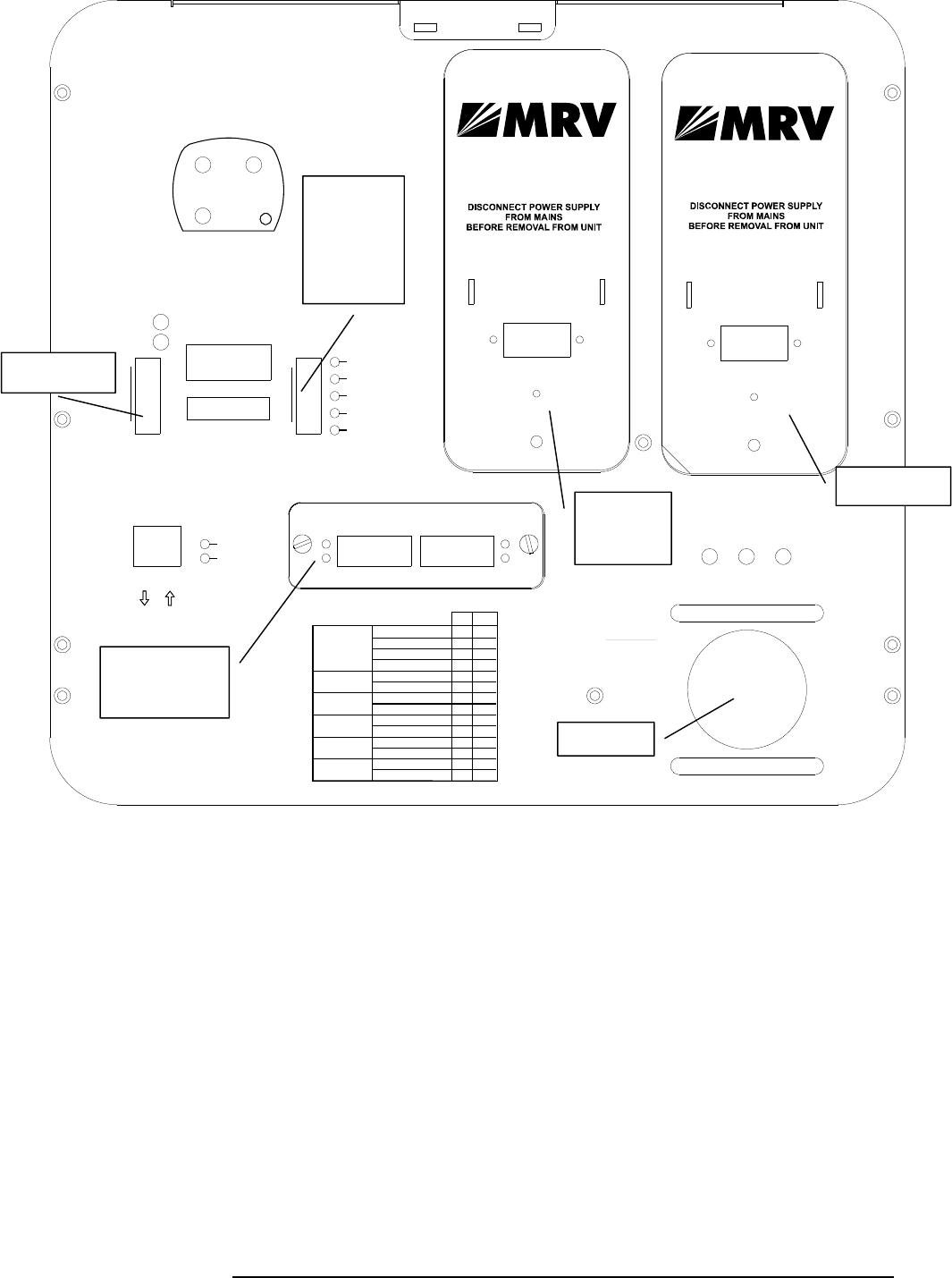
Figure 1.4: TS5000/G-F with a redundant power supply Panel Schematic
N
ot in use
Redundant PS