


MRV Communications, Inc. – Installation Manual
29
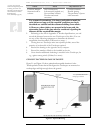
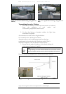
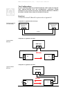
Figure 2.10: Extended Wall Mounting (using JMP and
MO62C)
Figure 2.11: Angle Bracket Mounting (using JMP and
M001)
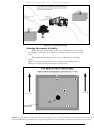
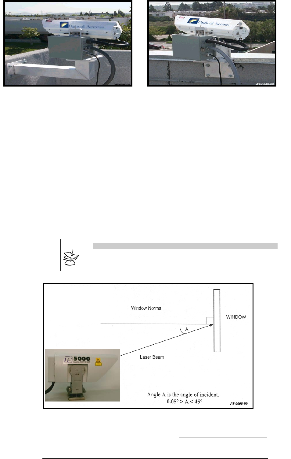
Transmitting through a Window
1. Determine the number of surfaces the beam transits or is reflected
from, the reflectivity of each surface, and
condensation/precipitation collection areas.
2. Use the data below to determine whether the light beam
attenuation is acceptable.
4% attenuation for each surface of light reflection.
15% attenuation for a double pane window.
Attenuation due to tint in windowpane must be taken into
consideration in choosing the right TereScope model. (The %
attenuation depends on the tint and must be measured.)
3. Ensure that the angle of incidence
3
of the beam striking the
windowpane is between 1º and 45º.
Note
On high buildings, for indoor window installation, the user should consider
that occasionally the window-cleaning elevator might block the link beam.
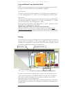
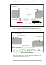
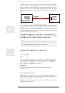
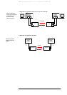
Figure 2.12 shows the arrangement for transmitting through a window
2
Angle which the light beam makes with the perpendicular to the windowpane
Figure 2.12:
A
rrangement for transmitting through a windo
w
.