


MRV Communications, Inc. – Installation Manual
18
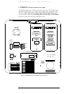
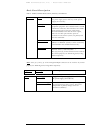
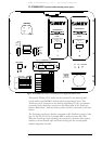
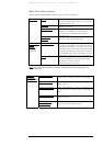
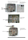
Back Panel Description
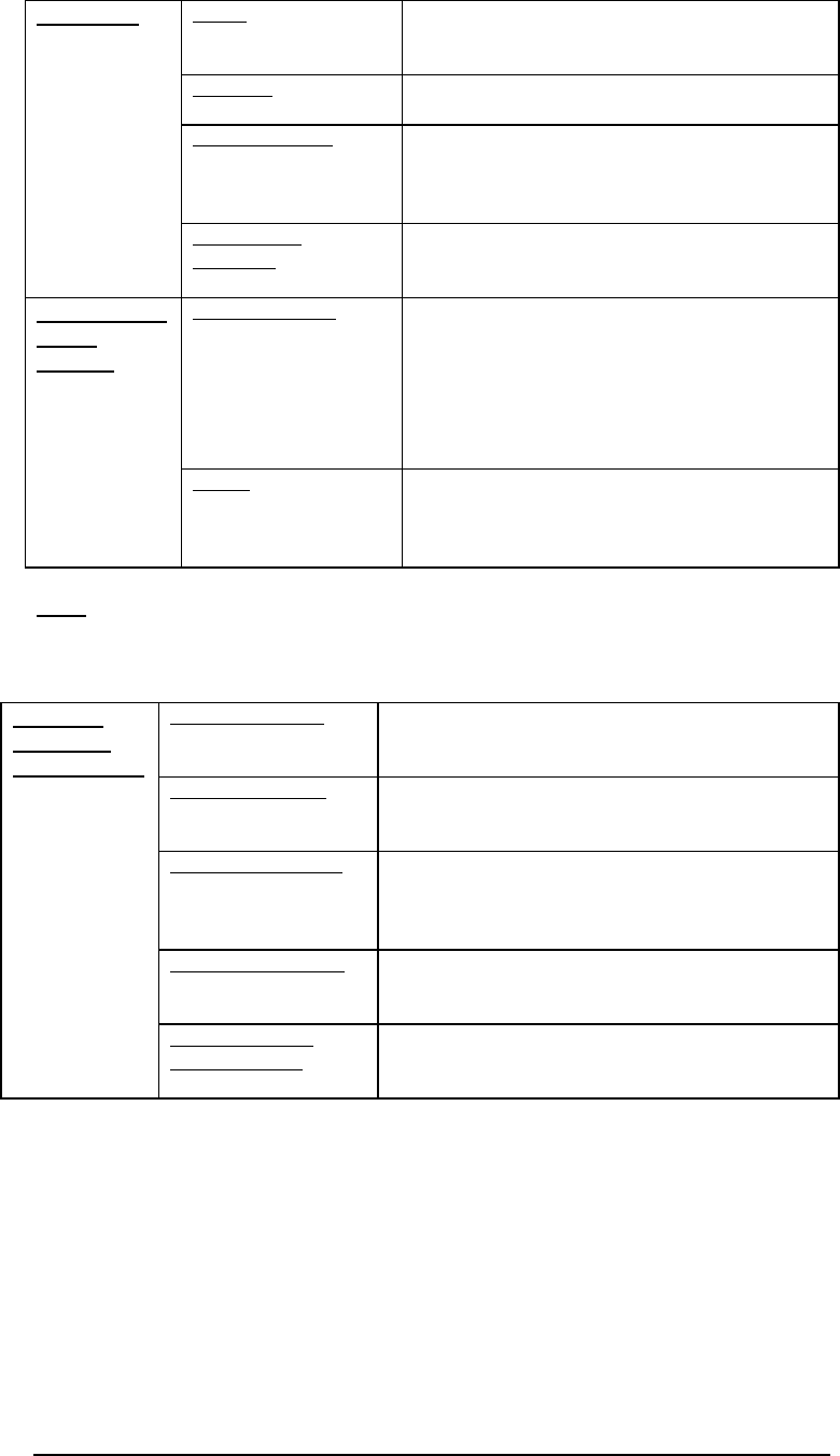
Table 4: TS5000/ETH Model Back Panel Controls, Interfaces, and Indicators
Note:
Pins (4,5) of the main RJ45 connector can be used for dry contact purposes, for
Airlink flag alarm.
Air RX Link LED Green LED indicates that a signal is received by the
Airlink receiver. Switches ON at the threshold level
Air RX Data LED Yellow LED indicates Data transfer through the
Airlink receiver
10Base-T Link LED Green LED indicates a signal is received by the
10BaseT interface. Switches ON at the threshold
level
10Base-T Data LED Yellow LED indicates Data transfer through the
10BaseT interface
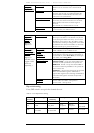
Indicators
(7-segment
display, LEDs)
Optical Power 7-
segment display
Digital readout indicates in mV the Optical Power
level received by the Airlink receiver
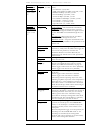
Power Power source Terminal Block (Main or UPS).
AC power supply (100 to 240 Vac) or DC power
supply (35 to 60 Vdc)
10Base-T
Copper interface (RJ45) for STP cables.
MDI-X connection.
Remote Monitor Connection to an optional Remote Status
Monitor or to RSM-DC (for Dry Contact
connection) (not included in the standard
transceiver kit)
Connectors
Management
(10baseT)
Connection to 10Base-T SNMP management
interface. Pins 1,2: TX and 3,6 RX.
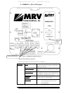
IP address set up When the Switch toggle is on OFF position, the
TereScope’s IP address is the default one (shown
on the back panel label: 10.0.0.101). To set a new
IP address, please refer to the “IP address setting
procedure for TereScope management card” file
in the Manuals CD. The new IP address is valid
only after the TereScope is powered off and on.
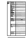
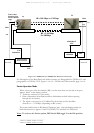
Selectors (DIP
Switch
Toggles) --
shown on
Figure 1.8
Fusion
This switch enables working with MRV’s Fusion
system. For additional info see page 8 Toggle
#10 OFF: Fusion Non Active:
Toggle #10 ON: Fusion active.