


MRV Communications, Inc. – Installation Manual
23
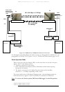
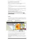
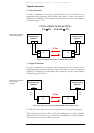
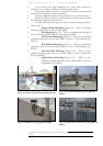
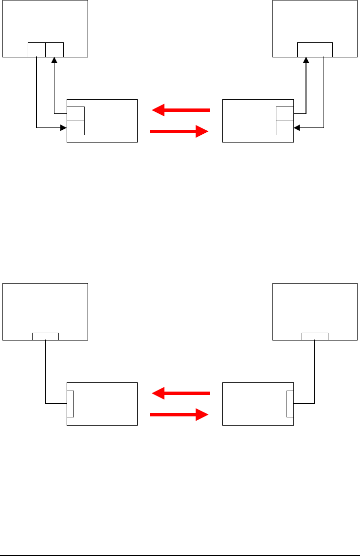
Typical Connection
1 - Fiber Connection
In order to implement a connection, each transceiver must be connected to the
peripheral/testing equipment through fiber optic cables. A correct connection is
notified by the display on the back panel of the transceiver (see the section Display
and Results pages 37 - 38).
IT IS A CROSS CONNECTION:
TX RX AND RX TX
Peripheral/Testing
Equipment
UWIN
RX
TX
TX RX
Peripheral/Testing
Equipment
UWIN
RX
TX
TXRX
IR link
Figure 1.14: Typical Connection for Models 155 and 155-F
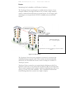
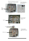
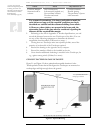
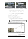
2 - Copper Connection
In order to implement a connection, each transceiver must be connected to the
peripheral/testing equipment through a 2 pairs STP cable. A correct connection is
notified by the display on the back panel of the transceiver (see the section Display
and Results pages 37 and 38).
IR link
Peripheral/Testing
Equipment
UWIN
10BaseT
10BaseT
STP
cable
Peripheral/Testing
Equipment
UWIN
10BaseT
10BaseT
STP
cable
Figure 1.15: Typical Connection for Models ETH and 4U1 (4E1 or 4T1)
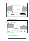
For 4E1/4T1 the 4 channels (or less as required) are to be connected separately.
When testing the model 4U1 (4E1 or 4T1), the matching ports on the two TS5000
heads must be connected, for e.g, if Channel A is connected on one head, Channel
A must be connected on the other head as well.
Scheme of the Connection
to peripheral equipment
Scheme of the Connection
to the peripheral
equipment
TS
T
S
TS
TS