


MRV Communications, Inc. – Installation Manual
49
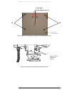
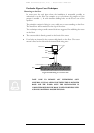
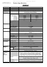
Procedure:
1. Find the horizontal and vertical Beam edges (H1, H2, V1, V2) by
obtaining a reading between 200 and 300 on the 7-segment display.
2. Set successively the remote transceiver in the middle of
the two segments [H1, H2] and [V1, V2].
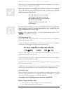
H1 H2
V1
V2
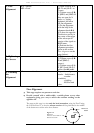
Important: Do
not
in all cases select the head position for which the DVM reading
is maximum! The best position of alignment is the beam center.
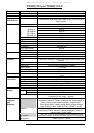
To determine the horizontal beam edges H1 and H2, move slowly left and right
the local transceiver until the digital readout on the remote unit becomes 200.
Locate these two points relating to reference points on the opposite site looking
through the telescope. Set the remote transceiver - moving the local transceiver - at
the middle of these two reference points.
H1 H2
V1
V2
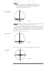
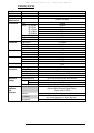
Repeat this process for the vertical positioning (middle of segment [V1,V2]).
H1
H2
V1
V2
Position at the beginning
(after the coarse alignment)
Position after the horizontal
aiming
Final position after the
vertical aiming
Fi
g
ure 6.8
Figure 6.9
Figure 6.10