


16
MultiModemBA User Guide
1.6 Power
Power is supplied through an AC power transformer terminated with a standard two-prong plug. The
transformer supplies low voltage AC to the modem, and plugs into any conventional 115 volt AC, 60
Hz, two-prong power outlet (240 volts AC, 50Hz, .3 Amp for International modems). The power
transformer supplied with the modem is the only one that should be used. Use of any other
transformer could cause damage to the modem. A Power On/Off switch is located on the back of the
modem.
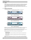
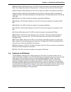
1.7 Modem LED Indicators
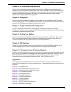
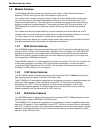
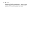
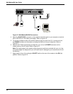
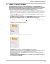
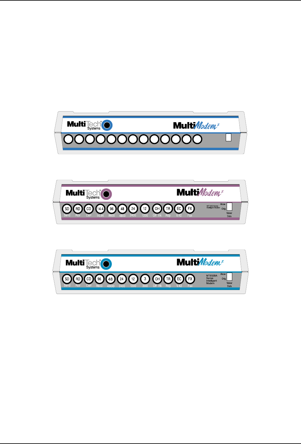
The MultiModem diagnostic LED indicators are shown in Figures 1-1a, 1-1b, and 1-1c.
FXECTROH249614.419.224.028.8CDRDSD
FaxV.42RdyOff Hk2400960014.4K19.2K24.0K28.8KCarrRcvSend
MT2834BA
Series
Intelligent
Modem
Voice/
Data
Answ
Orig
Figure 1-1a. MT2834 LED Display
Figure 1-1b. MT1432 LED Display
Figure 1-1c. MT932 LED Display
(SD) Send (Transmit) Data. This LED blinks when data is being transmitted, on for a space, off for a
mark. The state of this LED matches the TD circuit on Pin 2 of the RS-232C/V.24 interface.
(RD) Receive Data. This LED blinks when data is being received, on for a space, off for a mark. The
state of this LED matches that of the RD circuit on Pin 3 of the RS-232C/V.24 interface.
(CD) Carrier Detect. This LED is lit when a valid carrier tone has been detected.
2834 Models Only:
When the modem is connected at 33,600 bps, the 28.8 LED rapidly blinks at approximately 5
blinks per second.
When the modem is connected at 31,200 bps, the 28.8 LED blinks slowly at approximately 1
blink per second.
(28.8) 28,800 bps. (2834 models only) This LED is lit when the modem is connected at 28,800 bps.
Note: if the modem falls back to 26.4K bps while in V.34 mode, both the 28.8 and 24.0 LEDs light.