


21
Chapter 2 - Installation and Connection
2.2 Installation
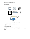
The installation of the modem consists of making the physical connections necessary to render the
modem functional with your computer. This includes making the proper serial, phone line, and power
connections. Unless otherwise noted, these instructions apply to all models of the BA series.
2.2.1 Safety Warnings
1 Never install telephone wiring during a lightning storm.
2 Never install telephone jacks in wet locations unless the jack is specifically designed for wet
locations.
3 Never touch uninsulated telephone wires or terminals unless the telephone line has been
disconnected at the network interface.
4 Use caution when installing or modifying telephone lines.
5 Avoid using a telephone (other than a cordless type) during an electrical storm. There may be a
remote risk of electrical shock from lightning.
6 Do not use the telephone to report a gas leak in the vicinity of the leak.
7 Ports which are connecting to other apparatus are defined as SELV. To ensure conformity with
EN 41003, ensure that these ports are only connected to the same type on other apparatus.
2.2.2 Installation Procedure
The following procedures will guide you through the physical connections required to make your
modem operational. Software loading is covered later in this guide.
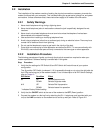
Step Procedure
1 Verify that the settings for DIP-Switch #5 and DIP-Switch #10 match those of your system
configuration.
The 16-position DIP-Switch (numbered 1-16) is accessible through a cut-out on the right side (as
the LEDs are facing you) of the modem chassis. For a full description of all DIP-Switch Settings,
refer to Chapter 9.
DIP-Switch Condition Effect
#5 UP* Selects Answer mode
DOWN Selects Originate mode
#10 UP* Selects Dial-Up operation
DOWN Selects Lease Line operation
* indicates Factory Default setting
2 Verify that the ON/OFF switch at the rear of the modem to the OFF (Down) position.
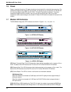
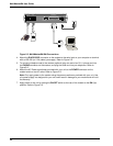
3 Connect the modem to a dial-up line by attaching the RJ-11 telephone cord (provided with your
unit) to the LINE connector on the modem and to a dial-up wall jack. Refer to Figure 2-2.