


Chapter 2 Using the SCXI-119X
© National Instruments Corporation 2-3 SCXI-1190/1191/1192 User Manual
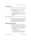
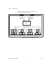
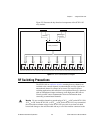
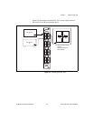
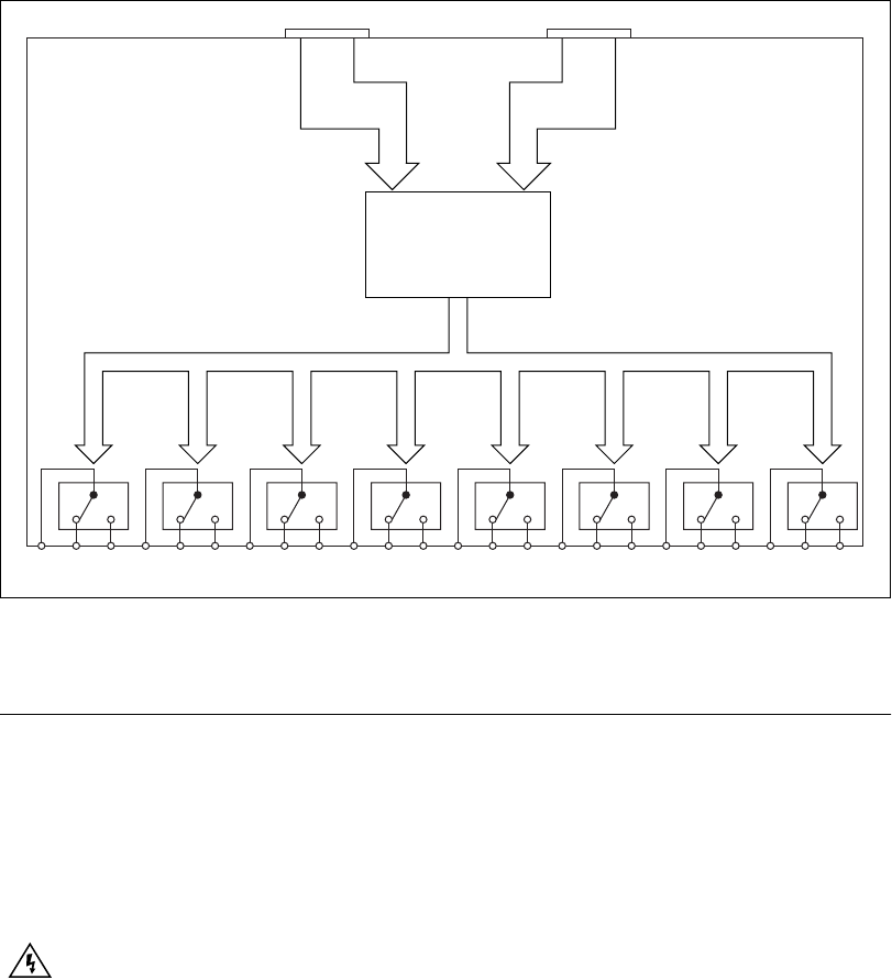
Figure 2-2 illustrates the key functional components of the SCXI-1192
relay module.
Figure 2-2.
SCXI-1192 Module Block Diagram
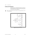
RF Switching Precautions
The SCXI-119X are reflective switches, meaning that any channels not
switched to the common channel are unterminated, and any signal on an
unterminated channel is reflected to its source. For most low-power
switching applications, this reflectionis not a problem. However, operation
with an unterminated output can damage some high-power RF sources.
Consult your RF source documentation for more information about
connecting to unterminated channels.
Warning
Do not exceed the channel-to-ground rating of 24 V
rms
or DC on the SCXI-1190,
30 V
rms
or DC for the SCXI-1191, or 30 V
rms
or DC for the SCXI-1192. Any connections
that exceed the maximum voltage for the SCXI-119X can result in an electrical shock
hazard and damage to the switch module and any or all of the modules connected to the
SCXIbus
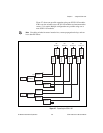
NC0com0 NO0 NC1com1 NO1 NC2com2 NO2 NC3com3 NO3 NC4com4 NO4 NC5com5 NO5 NC6com6 NO6 NC7com7 NO7
Relay Controller
Rear Signal
Connector