


Chapter 2 Using the SCXI-119X
© National Instruments Corporation 2-9 SCXI-1190/1191/1192 User Manual
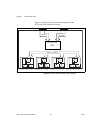
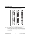
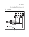
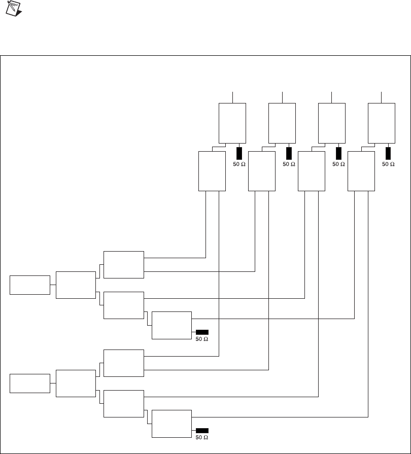
Figure 2-7 shows one possible expansion using two SCXI-1192 modules.
In this case, the switches on two SCXI-1192 modules are interconnected to
create a 2 × 4 matrix. Multiple configurations are possible using one or
more SCXI-1192 modules.
Note
Cascading switches increases insertion loss, creates propagations delays, and can
have other RF effects.
Figure 2-7. Expanding the SCXI-1192
Instrument
1
Switch 0
Switch 1
Switch 2
Switch 3
Instrument
2
Switch 4
Switch 5
Switch 6
Switch 7
Switch 0
Switch 1
Switch 2
Switch 3
Switch 4
Switch 5
Switch 6
Switch 7
RF
Source 1
RF
Source 2
RF
Source 3
RF
Source 4
com B
0B
1B