Chapter 6 Using Your Serial Hardware
© National Instruments Corporation 6-3 Serial Hardware and Software for Windows
Two-Wire Mode: TXRDY Auto Control
In this mode, the serial hardware transparently enables the transmitter and
receiver in a two-wire system. Use this mode to remove the burden of flow
control from your application. By connecting the transmitter to the
TXRDY
(Transmit Ready) line, the hardware enables the transmitter for
each byte to be transmitted. Also, the hardware disables the receiver
whenever the transmitter is enabled, so you do not receive the packets sent
from your transmitter.
Note
When you are communicating with a two-wire device, National Instruments
recommends that you use the two-wire TXRDY
auto control mode. Because this mode
handles the transmitter/receiver enabling for a two-wire connection in your hardware,
it reduces the software overhead required to perform this operation in your application
program.
For more information about serial communication in two- or four-wire modes, refer to the
Serial Communication Issues sectioninAppendixB,Serial Port Information.
Setting the Transceiver Control Mode
Windows 2000
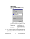
To set the transceiver control mode, use the Windows 2000 Device
Manager. For instructions on how to use the Device Manager, refer to the
chapter with installation instructions for your hardware platform. The mode
you select in the Device Manager is automatically configured when you
open a port on a serial interface.
Windows Me/9x
To set the transceiver control mode, use the Windows Me/9x Device
Manager. For instructions on how to use the Device Manager, refer to
chapter with installation instructions for your hardware platform. The mode
you select in the Device Manager is automatically configured when you
open a port on a serial interface.
You can also set the hardware transceiver control mode from within a DOS
application. For each port you want to control, writethe control byte for the
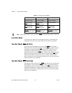
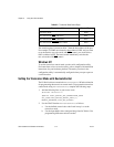
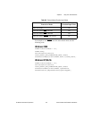
mode you want to select to the scratch register of the UART. Table 6-2
shows the control bytes for each mode.


