


Chapter 3 Connecting the Signals
DAQCard-1200 User Manual 3-4 ni.com
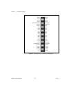
The connector pins are grouped into AI signal pins, AO signal pins, DIO
signal pins, TIO signal pins, and power connections. Signal connection
guidelines for each group is described in the following sections.
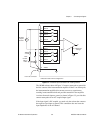
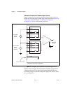
Connecting Analog Input Signals
Pins 1 through 8 are analog input signal pins for the 12-bit ADC. Pin 9,
AISENSE/AIGND, is an analog common signal. You can use this pin as a
signal ground connection to the DAQCard-1200 in RSE mode or as a return
path in NRSE mode. Pin 11, AGND, is the bias current return point for
differential measurements. Pins 1 through 8 are tied, through 4.7 kΩ series
resistances, to the eight single-ended AI channels of the input multiplexer.
Pins 2, 4, 6, and 8 are also tied to an input multiplexer for DIFF mode.
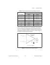
The signal ranges for inputs ACH<0..7> at all possible gains are shown in
Table 3-2. Exceeding the input signal range does not damage the input
circuitry as long as the maximum input voltage rating of ±35 V powered on
and ±25 V powered off is not exceeded. The DAQCard-1200 is guaranteed
to withstand inputs up to the maximum input voltage rating.
Caution
Exceeding the input signal range distorts input signals. Exceeding the maximum
input voltage rating may damage the DAQCard-1200 and the computer. NI is not liable for
damage resulting from such signal connections.
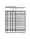
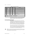
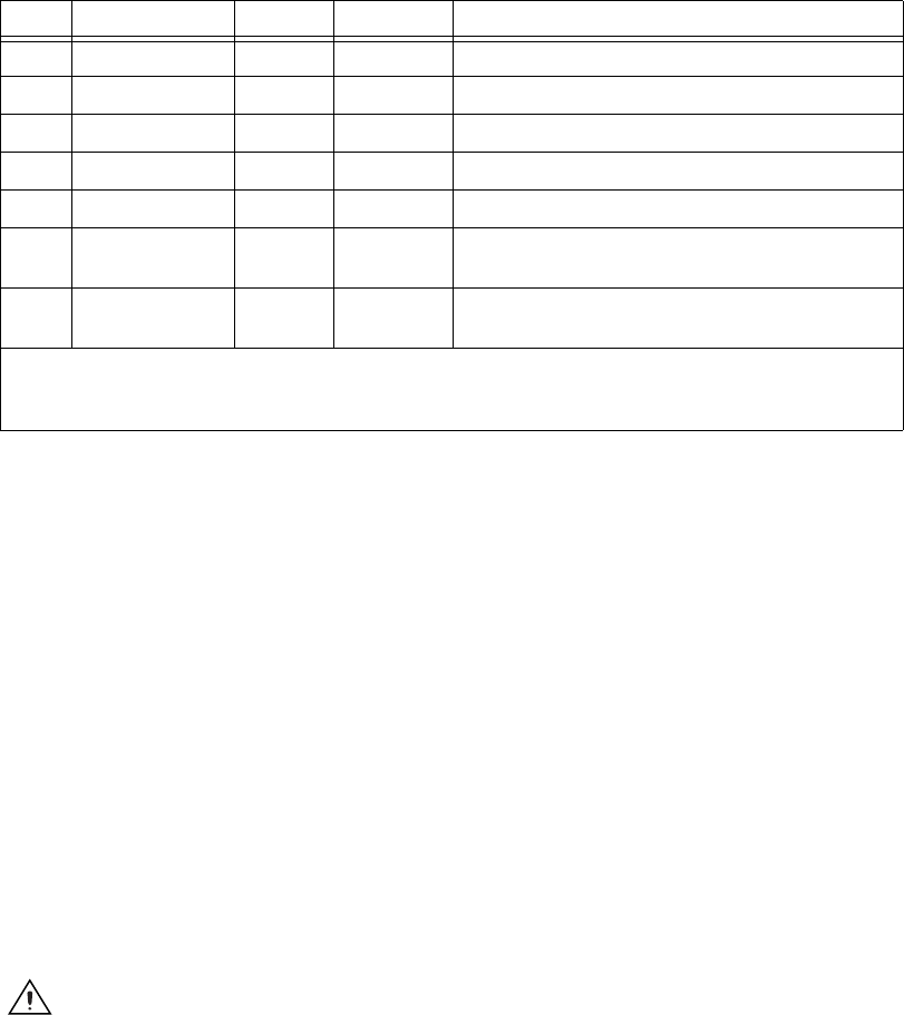
44 GATB1 DI DGND Gate B1—External control signal for gating counter B1.
45 CLKB1 DI DGND Clock B1—External control clock signal for counter B1.
46 OUTB2 DO DGND Counter B2—Voltage output signal of counter B2.
47 GATB2 DI DGND Gate B2—External control signal for gating counter B2.
48 CLKB2 DI DGND Clock B2—External control clock signal for counter B2.
49 +5 V DO DGND +5 Volts—Fused for up to 1 A of +5 V supply, but limit
current to 250 mA.
50 DGND N/A N/A Digital Ground—Voltage ground reference for the digital
signals and the +5 V supply.
* Indicates that the signal is active low.
AI = Analog Input DI = Digital Input DIO = Digital Input/Output
AO = Analog Output DO = Digital Output N/A = Not Applicable
Table 3-1. Signal Descriptions (Continued)
Pins Signal Name Direction Reference Description