


Chapter 3 Connecting the Signals
© National Instruments Corporation 3-27 DAQCard-1200 User Manual
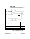
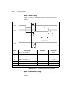
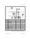
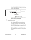
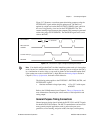
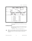
Figure 3-17 illustrates a waveform generation timing sequence using the
EXTUPDATE* signal and the delayed update mode. The DACs are
updated by a high level on the DAC OUTPUT UPDATE signal, which in
this case is triggered by a low level on the EXTUPDATE* line. The
counter-interrupt signal interrupts the computer. This interrupt is generated
on the rising edge of EXTUPDATE*. The DACWRT signal writes a new
value to the DAC.
Figure 3-17.
EXTUPDATE* Signal Timing for Updating DAC Output
Note
You should configure both DACs in either immediate update mode or in later update
mode, but not in a combination of the two modes. Although you can configure the DACs
in a combination of modes, doing so can result in glitches on the immediate update DAC
if the update rate on the waveform DAC is high. Refer to the Analog Output section in
Chapter 4, Theory of Operation, for details on this behavior.
The following rating applies to the EXTCONV*, EXTTRIG, OUTB1, and
EXTUPDATE* signals.
• Absolute maximum voltage input rating –0.5to5.5Vwithrespect
to DGND
Refer to the NI-DAQ manual or to Chapter 4, Theory of Operation,for
more information concerning the various modes of data acquisition and
analog output.
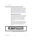
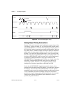
General-Purpose Timing Connections
General-purpose timing signals include the GATE, CLK, and OUT signals
for the three 82C53(B) counters. The 82C53 counter/timers can be used for
many general-purpose applications such as pulse and square wave
generation; event counting; and pulse-width, time-lapse, and frequency
DACWRT
Counter Interrupt
DAC OUTPUT
UPDATE
EXTUPDATE*
t
w
50 ns min