


Chapter 3 Connecting the Signals
DAQCard-1200 User Manual 3-16 ni.com
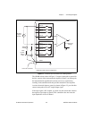
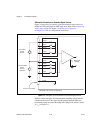
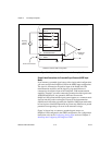
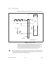
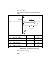
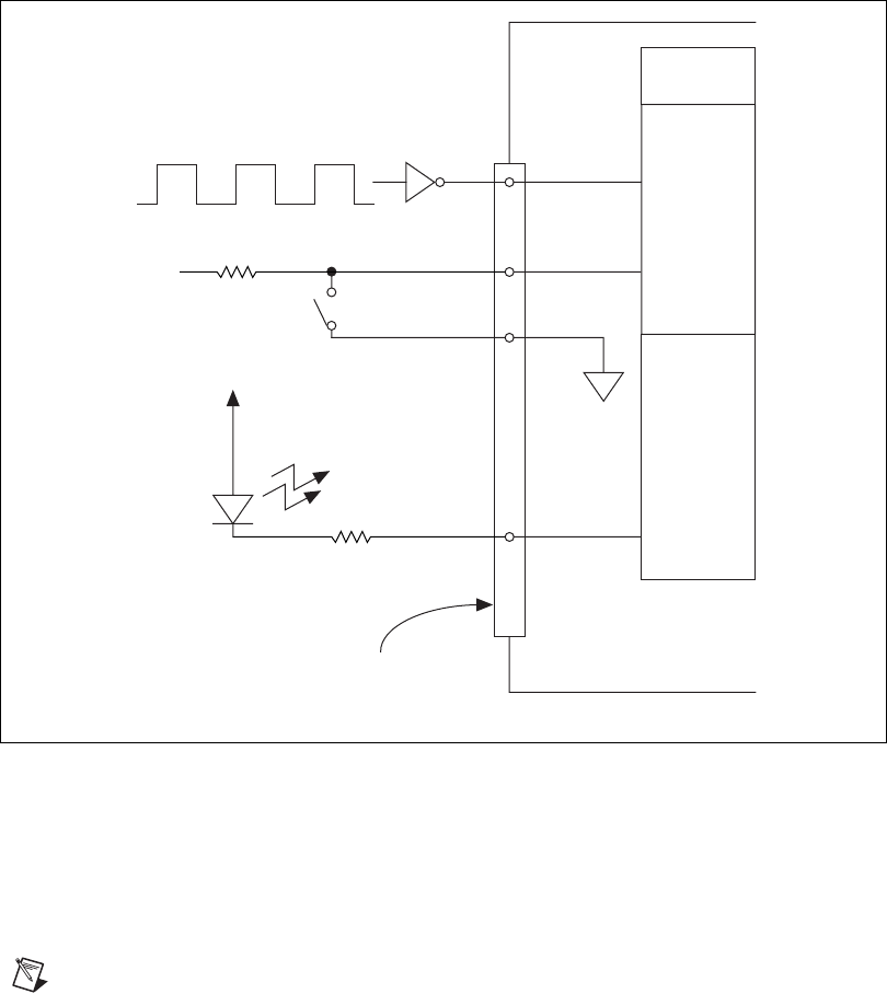
Figure 3-8 illustrates signal connections for three typical DIO applications.
Figure 3-8. Digital I/O Connections
In Figure 3-8, port A is configured for digital output, and ports B and C are
configured for digital input. Digital input applications include receiving
TTL signals and sensing external device states such as the switch in
Figure 3-8. Digital output applications include sending TTL signals and
driving external devices, such as the LED shown in Figure 3-8.
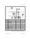
Note
The 82C55A has only one configuration register. Therefore, you must program the
direction (input/output) of all ports before writing or reading from them to prevent data loss
caused by the ports being reset to their default state.
Port C
PC<0..7>
Port B
PB<0..7>
Port A
PA<0..7>
TTL Signal
+5 V
+5 V
LED
I/O Connector
DAQCard-1200
30 PA0
DGND
13
29 PB7
22 PB0