


Chapter 3 Connecting the Signals
DAQCard-1200 User Manual 3-28 ni.com
measurement. For these applications, the CLK and GATE signals at the
front I/O connector control the counters. The single exception is counter
B0, which has an internal 2 MHz clock. Refer to the DAQCard-1200
Register-Level Programmer Manual for programming information.
The GATE, CLK, and OUT signals for counters B1 and B2 are available at
the I/O front connector. The GATE and CLK pins are internally pulled up
to +5 V through a 100 kΩ resistor. Refer to Appendix A, Specifications,for
signal voltage and current specifications.
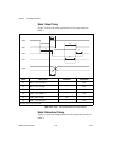
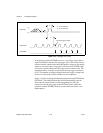
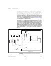
You perform pulse and square wave generation by programming a counter
to generate a timing signal at its OUT output pin. Perform event counting
by programming a counter to count rising or falling edges applied to any of
the 82C53 CLK inputs. You can then read the counter value to determine
the number of edges that have occurred. You can gate counter operations on
and off during event counting. Figure 3-18 shows connections for a typical
event-counting operation in which a switch is used to gate the counter on
and off.
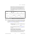
Figure 3-18. Event-Counting Application with External Switch Gating
+5 V
Signal
Source
Switch
I/O Connector
13 DGND
CLK
GATE
OUT
Counter (from Group B)
DAQCard-1200