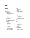
Index
DAQCard-1200 User Manual I-2 ni.com
exceeding maximum input voltage ratings
(caution), 3-4
floating signal sources, 3-6
ground-referenced signal sources, 3-6
input configurations, 3-7
instrumentation amplifier, 3-5
pins, 3-3
recommended input configurations
(table), 3-7
single-ended connections
floating signal sources (RSE
configuration), 3-11
grounded signal sources (NRSE
configuration), 3-12
purpose and use, 3-11
when to use, 3-11
types of signal sources, 3-6
analog output
circuitry, 4-10
DAC timing, 4-11
polarity
configuration, 2-6
settings (table), 2-5
power-on state, 4-11
signal connections, 3-14
specifications
dynamic characteristics, A-5
output characteristics, A-4
stability, A-5
transfer characteristics, A-4
voltage output, A-5
theory of operation, 4-10
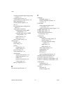
B
bus interface specifications, A-7
C
calibration
EEPROM storage, 5-1
loading calibration constants, 5-1
overview, 5-1
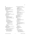
CLK signals
general-purpose timing signal
connections, 3-27
timing requirements signals (figure), 3-31
CLKB1 signal (table), 3-4
CLKB2 signal (table), 3-4
common-mode signal rejection
considerations, 3-13
configuration
analog input
analog I/O settings (table), 2-3
default settings, 2-3
exceeding maximum ratings
(caution), 2-3
input modes, 2-4
input polarity, 2-4
analog output polarity, 2-6
counter/timers, 2-6
digital I/O, 2-6
PC Card, C-1
typical configuration (figure), 2-2
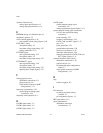
contacting National Instruments, E-2
conventions used in the manual, xi
Counter 0 on 82C53(A) counter/timer, 3-22
Counter 1 on 82C53(A) counter/timer, 3-22
counter/timers
configuration, 2-6
theory of operation, 4-3
customer
education, E-1
technical support, E-1


