


© National Instruments Corporation 9 Getting Started with R Series Intelligent DAQ
Adding Analog Output to the FPGA Application
To expand the LabVIEW FPGA application to include analog output, complete the following steps:
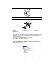
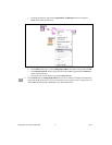
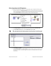
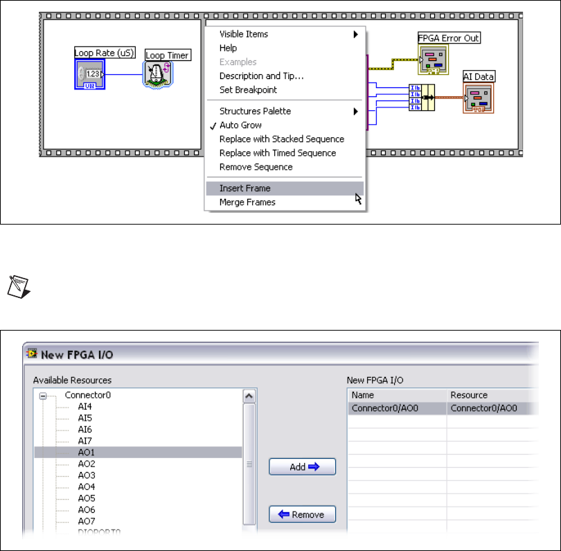
1. On the block diagram of Analog Input (FPGA).vi, insert a new frame between the first and second
frames of the Flat Sequence structure by right-clicking the divider between the first two frames and
selecting Insert Frame from the shortcut menu, as shown in the following figure.
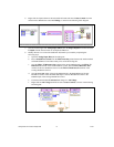
2. In the Project Explorer window, right-click the FPGA target and select New»FPGA I/O.
3. In the New FPGA I/O dialog box, expand Connector0 and select AO0.
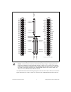
Note This example reflects the naming conventions and graphic interface of LabVIEW 8.5. Items
such as FPGA I/O resources may appear differently if you are using earlier versions of LabVIEW.
4. Click Add, then click OK.
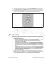
5. Click Connector0/AO0 in the Project Explorer window and drag it into the second frame of the
Flat Sequence structure on the block diagram of the FPGA VI. The FPGA I/O Node is created
automatically.