


© National Instruments Corporation 4-1 PCI-MXI-2 for Linux
4
VME-MXI-2 Configuration
and Installation
This chapter contains the instructions to configure and install the
VME-MXI-2 module. This chapter applies only if you ordered the
VME MXI-2 kit. If you ordered the VXI MXI-2 kit, you should refer to
Chapter 3, VXI-MXI-2 Configuration and Installation.
Caution Electrostatic discharge can damage several components on your VME-MXI-2
module. To avoid such damage in handling the module, touch the antistatic plastic package
to a metal part of your VMEbus chassis before removing the VME-MXI-2 from the
package.
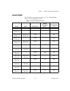
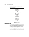
Configure the VME-MXI-2
This section describes how to configure the following options on the
VME-MXI-2:
• VMEbus A16 base address
• VME-MXI-2 intermodule signaling
• MXIbus termination
• Configuration EEPROM
• Onboard DRAM
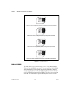
The VME-MXI-2 automatically detects if it is located in the first slot of
the chassis to perform the VMEbus System Controller functions. It is not
necessary to configure the VME-MXI-2 System Controller option. The
module can be installed in any slot of a VMEbus chassis.
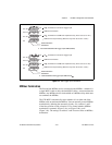
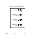
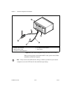
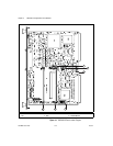
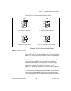
Figure 4-1 shows the VME-MXI-2. The drawing shows the location and
factory-default settings of the configuration switches and jumpers on the
module.