


Appendix C Advanced Hardware Configuration Settings
© National Instruments Corporation C-3 VXI-USB User Manual
When switch S5 is set so that the VXI-USB receives the SMB CLK10
signal, you have the option to add a 50 Ω termination to the signal by setting
switch S4. S4 is unused when S5 is configured to drive the external CLK
SMB signal.
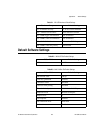
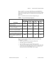
Table C-1 summarizes the most common configuration types.
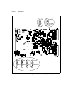
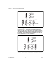
Figure C-2 shows the default settings for the CLK10 switches. This
configuration is as follows:
• CLK10 is generated from the onboard oscillator (S2).
• The CLK10 signal is terminated (S4).
• The VXI-USB receives the external CLK10 signal (S5).
• The polarity of the CLK10 signal (S6) is irrelevant when the VXI-USB
receives the external CLK10 signal. However, it is configured to be
noninverted when the CLK10 SMB is used as output.
Table C-1. Common CLK10 Routing Configurations
Description
Switches
S2 CLK10
Source
S4
Terminate
S5
Direction
S6
Polarity
Generate internal CLK10 with
onboard oscillator
ONBRD N/A IN N/A
Generate internal CLK10 and drive
to external CLK SMB
ONBRD N/A OUT NON
Generate internal CLK10 and drive
inverted to external CLK SMB
ONBRD N/A OUT INV
Receive external CLK SMB and
drive to the backplane unterminated
SMB N IN N/A
Receive external CLK SMB with
50 Ω termination and drive to the
backplane
SMB Y IN N/A