


Appendix C Advanced Hardware Configuration Settings
VXI-USB User Manual C-4 ni.com
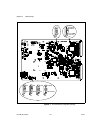
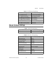
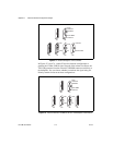
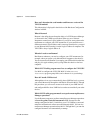
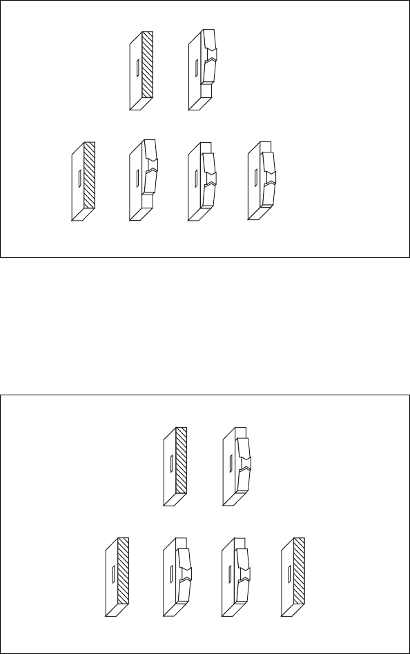
Figure C-2. Default Settings for CLK10 Switches
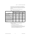
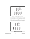
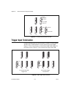
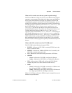
In Figures C-3 and C-4, switch S2 uses the alternate configuration to
generate the VXIbus CLK10 signal. Instead of the onboard oscillator, the
VXI-USB generates from the external CLK SMB connector and drives to
the backplane. You can choose whether to terminate the signal using S4.
Polarity remains irrelevant to these configurations.
Figure C-3. Receive External CLK SMB and Drive to the Backplane Unterminated
S3
S4 S5 S6
ON
OFF
OUT
IN
S2
From
Onboard
Oscillator
From SMB
CLK10 In
S1
Inverted
Noninverted
S3
S4 S5 S6
ON
OFF
OUT
IN
S2
From
Onboard
Oscillator
From SMB
CLK10 In
S1