


Appendix C Advanced Hardware Configuration Settings
© National Instruments Corporation C-5 VXI-USB User Manual
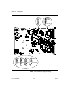
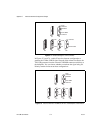
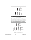
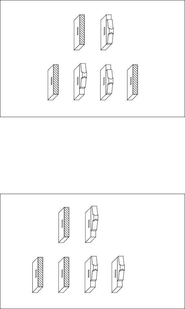
Figure C-4. Receive External CLK SMB with 50 Ω Termination
and Drive to the Backplane
Figures C-5 and C-6 show two configurations for driving the external CLK
SMB from the VXIbus CLK10 signal by changing switch S5 to its alternate
setting. Switch S2 must be in its default position for these configurations.
Signal termination is not an issue when driving the signal, so the position
of S4 does not matter. The difference between these two configurations is
whether to use inverted or noninverted polarity when driving the signal.
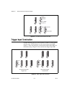
Figure C-5. Drive Inverted External CLK SMB
S3
S4 S5 S6
ON
OFF
OUT
IN
S2
From
Onboard
Oscillator
From SMB
CLK10 In
S1
S3
S4 S5 S6
OUT
IN
S2
From
Onboard
Oscillator
From SMB
CLK10 In
S1
Inverted
Noninverted