


4-44
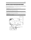
46. Mount the PCI Module #1 again to the NEC Express5800/ft series (see page 8-33
“Installing PCI Module”) and plug the power cord to the AC inlet B (for Group1). (The
POWER Switch LED will be turned on.)
47. Likewise, mount the PCI Module #2 to the NEC Express5800/ft series and plug the power
cord to the AC inlet A (for Group2).
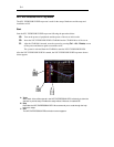
48. Shortly after you connect the both power cords, the BMC status LED on PCI Module #2
will start to blink.
When Password clear is completed, the BMC status LED will go off.
CHECK:
The BMC status LED blinks to show that synchronous processing is being
performed between the two modules. When this process is complete, Password has
also been cleared on PCI Module #2.
TIPS:
For the location of the AC inlet A, the AC inlet B, see “Names and Functions of
Components” in Chapter 2.
For the location of the BMC status LED, see “Names and Functions of
Components” in Chapter 2.
For description of the BMC status LED, see “LEDs” in Chapter 2.