


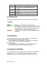
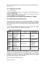

connection.
G1, G2
This is where you connect the Cat. 5e or better
Ethernet cable for 10/100/1000 Mbps Ethernet
connection
miniGBIC
This is where you connect the SFP module for fiber
connection.
Console
This is where you connect the RS-232 cable for CLI
management.
Power
This is where you connect the AC power cord.
2.3.
2.4.
2.5.
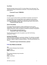
LED Function
This section explains the definition of the Switch’s LEDs on the front panel.
1. NP2724M
POWER (Green) LED lights up, it shows the system is powered up.
LINK/ACT(Green) LED lights up, it indicates a successful connection of that
port is established. Otherwise, it indicates the link is off or
no-link detected of that port. When the LED blinks, it
indicates the port is in activity and transmitting data;
1000Mbps (Amber) LED lights up only when the corresponding port works at
1000Mbps.
Reset Button
There is a Reset button on the front panel, which has two functionalities:
a) To restore switch configuration to factory defaults
Press the Reset button for more than 10 seconds, switch configuration
will be restored to factory defaults and then reboots.
b) To reboot switch
Press the Reset button for less than 10 seconds, switch will reboot.
Please note, you will lose unsaved change when doing this.
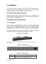
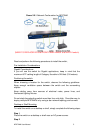
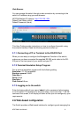
Installing the NP2724M
This section describes how to install and make connection to your NP2724M
Managed Switch. The following diagrams shows the a typical network
configuration, Figure 2.5.1 shows the network configuration for NP2724M
NP2724M User Manual 4