Reference Manual for the Model DG814 DSL Modem Internet Gateway
Setting Up the Hardware 2-7
ADSL through other wall jacks
1. Plug the “LINE” connection from the included microfilter into the wall jack.
2. Connect the “DSL” jack of the microfilter to the ADSL port of your gateway using the
telephone cable provided.
3. Connect the “PHONE” side of the microfilter to your telephone, using your existing telephone
cable.
A telephone can be attached to the second RJ-11 jack on your gateway. However, a microfilter
should be connected between the gateway and the telephone. Be careful to connect the microfilter
according to its markings, with the “LINE” side plugged into the gateway and the “PHONE” side
connected to your telephone.
If you have additional telephones, you will need to purchase additional microfilters and connect
them between the telephones and the wall jack. A microfilter is required for each telephone on the
line.
Connecting the Power Adapter
To connect the power adapter to the gateway:
1. Plug the connector of the power adapter into the 18 V AC adapter outlet on the rear panel of
the gateway.
2. Plug the other end of the adapter into a standard wall outlet.
3. Set the gateway’s Power switch to the ON position.
4. Verify that the PWR LED on the gateway is lit.
Verifying Power
After applying power to the gateway, complete the following steps to verify that power is correctly
applied:
1. When power is first applied, verify that the Power LED comes on.
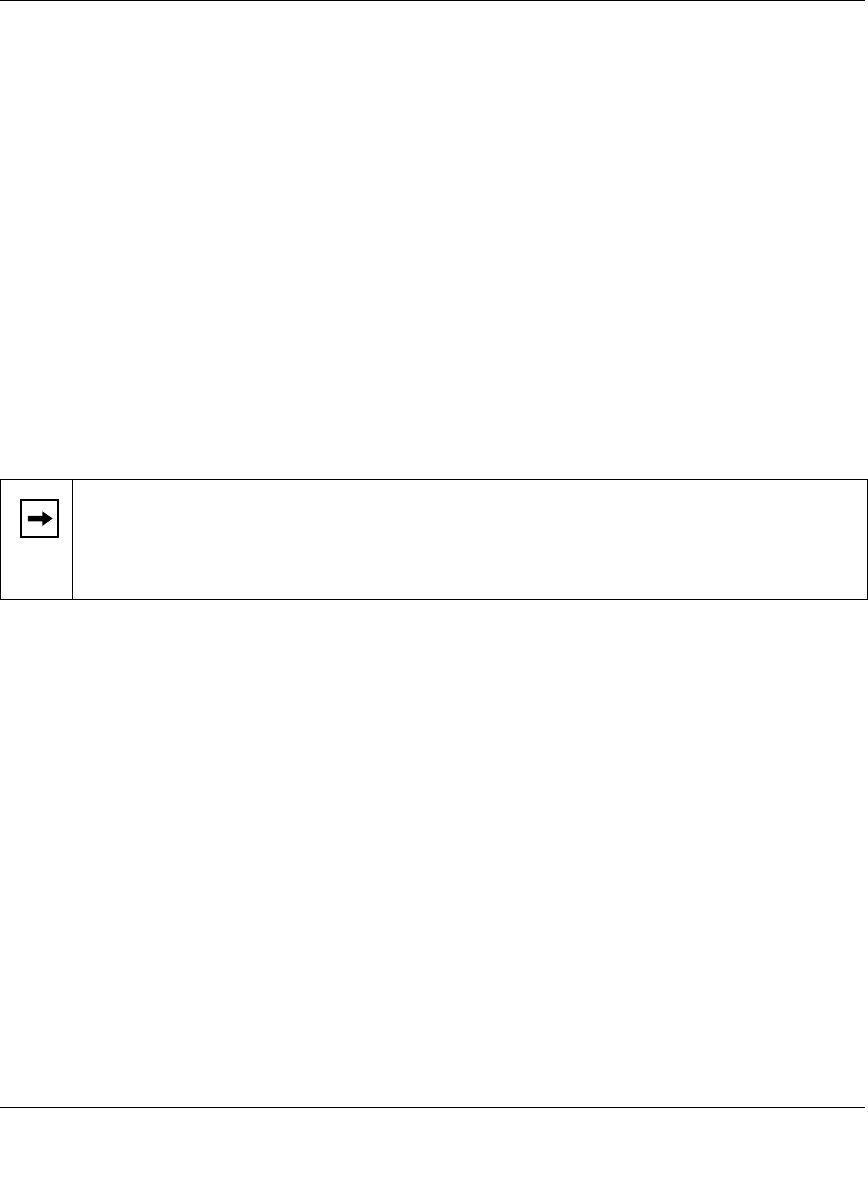
Note: Microfilters are required to isolate your ADSL signal from your telephone signal.
If microfilters are not used, or if they are connected backward, you may notice a
“ticking” noise on your telephone, and the performance of your ADSL line may be
affected.


