


NTI RACKMUX KVM Drawer with NODEMUX Switch
6
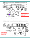
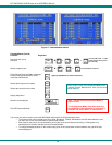
4. Connect the remaining input device and monitor interface cables from each CPU, making sure that cables from the each CPU
are connected to the NODEMUX switch at connectors with the same port numbers ("CPU 1" and "VIDEO 1 connectors,
"CPU 2" and "VIDEO 2" connectors...etc. )
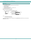
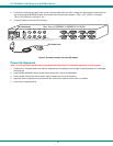
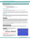
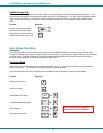
5. Connect the power cord to the IEC connector.
Figure 4- Connect the power cord and AC adapter
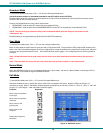
Power-Up Sequence
Note: It is very important that this power-up sequence be followed for all connected components to work properly.
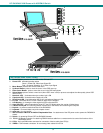
1. Using the key, unlock the drawer and slide the keyboard and LCD Display out far enough to raise the display to a comfortable
viewing angle.
2. Power ON the NODEMUX with the power switch located at the rear of the RACKMUX.
3. Power ON the KVM Drawer with the power switch located at the rear of the keyboard.
4. Adjust the screen's brightness and contrast with the controls also located on the monitor– as needed.
5. Power ON any attached CPUs.
IEC Power Cord
8 4 7 3 6 2 5 1
VIDEOVIDEO
NETWORK TECHNOLOGIESINC Tel:330-562-70701275 Danner Dr, Aurora, OH 44202 www.nti1.com
Rear View of NODEMUX in RACKMUX-V15-8UNV
CPU 4
CPU 3
CPU 2 CPU 1
CPU 8
CPU 7
CPU 6 CPU 5
IEC Connectxor