


NTI RACKMUX KVM Drawer with NODEMUX Switch
18
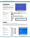
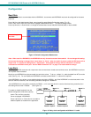
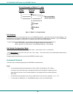
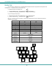
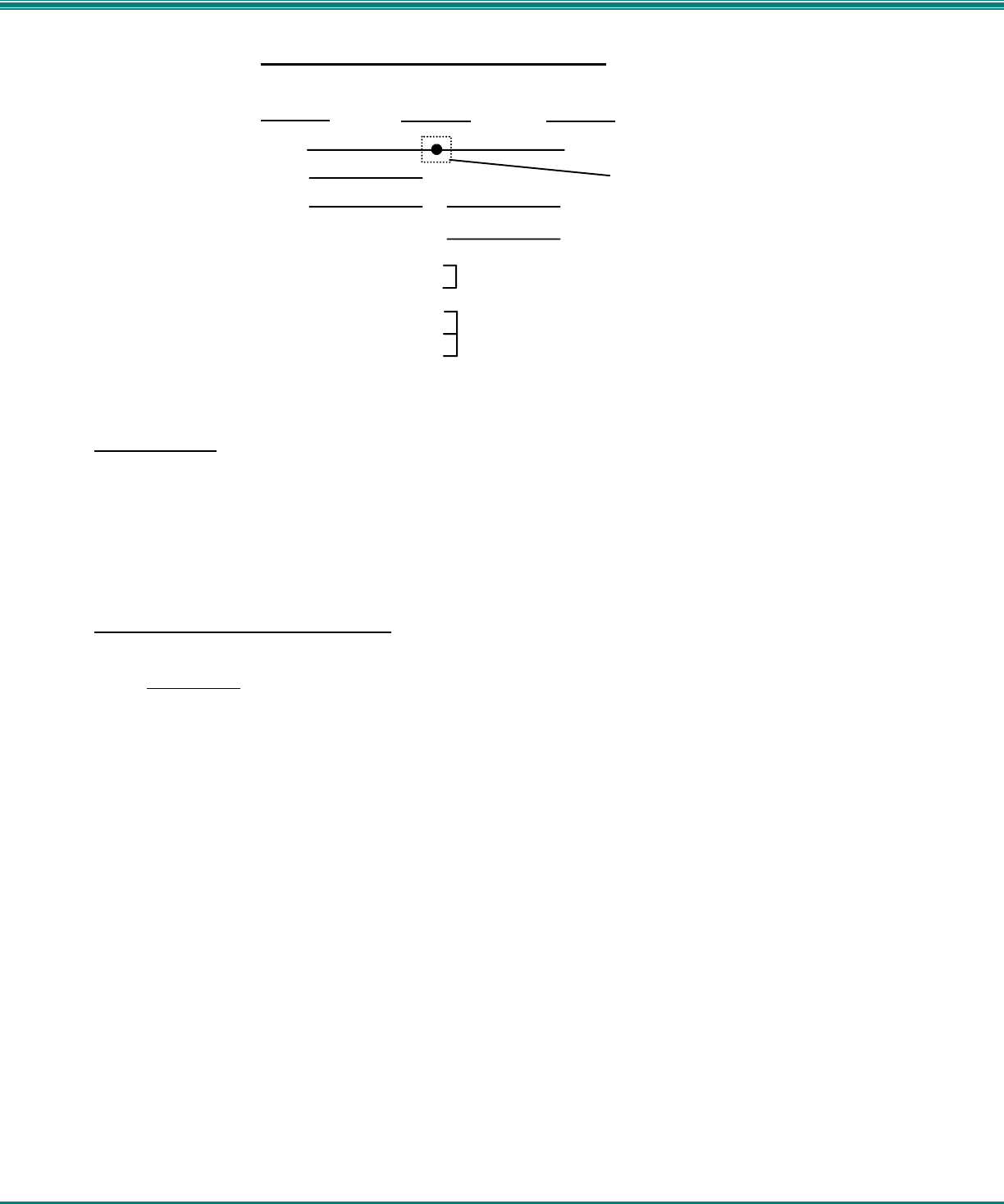
Figure 17- Matrix-Y-1 wiring schematic
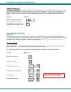
Unit Address
In order for a terminal to communicate with one or more NODEMUX switches, each switch must have a unique address. The
NODEMUX will only respond to commands from a terminal if its address is embedded in the command. Up to 15 NODEMUX
switches can be connected in a "daisy chain" to a terminal, each with its own unique address.
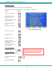
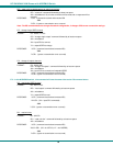
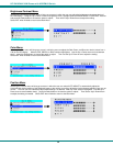
To set the address of the NODEMUX, from the Switch Configuration mode menu (Fig. 15 on page 17),
press <Tab> until the cursor bar moves to highlight "RS232 UNIT ADDRESS".
press <Up Arrow> or <Down Arrow> until the desired address (1-15) is selected.
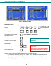
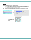
Exit Switch Configuration Mode
Once changes are made to the Switch Configuration menu, press <Enter> and <Y> to save them.
To exit without saving, press <Esc>, then <N>, then <Esc> again. The menu will return to the Administration Mode without
saving the changes made. .
Changes made will take effect the next time the NODEMUX is power cycled.
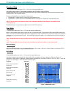
Command Protocol
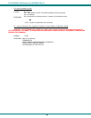
Terminal control commands supported by the NODEMUX are defined below.
Notes:
• All commands should be terminated with an <Enter> (ASCII 13) denoted by <CR>. When a
command is sent, the entire string is echoed back to the terminal along with a response from the
addressed unit as shown in the command definitions. Unit response will be sent within 500 msec
after <CR>.
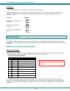
• All characters should be upper case, and all numbers below 10 should have a leading 0 (ex: 1 = 01).
• For units with one USER port (i.e. this NODEMUX switch), use 01 for the USER select.
(Unit #1)
(Source)
23
33
555
22
7
8
1
4
6
Jumper
Jumpers
Not connected to
source connector
(Unit #2)
9D Female9D Male 9D Male
Wiring Schematic of Matrix-Y-1 cable