


NTI RACKMUX KVM Drawer with NODEMUX Switch
16
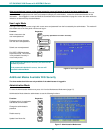
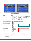
Help Mode
To enter Help Mode press the <F1> key from the Command Mode menu (page 11).
Help Mode displays a list of commands with a short explanation of their function. These lists are organized in pages for each
mode (i.e. COMMAND, EDIT, and SEARCH). The following options enable the user to quickly obtain information on any
command
.
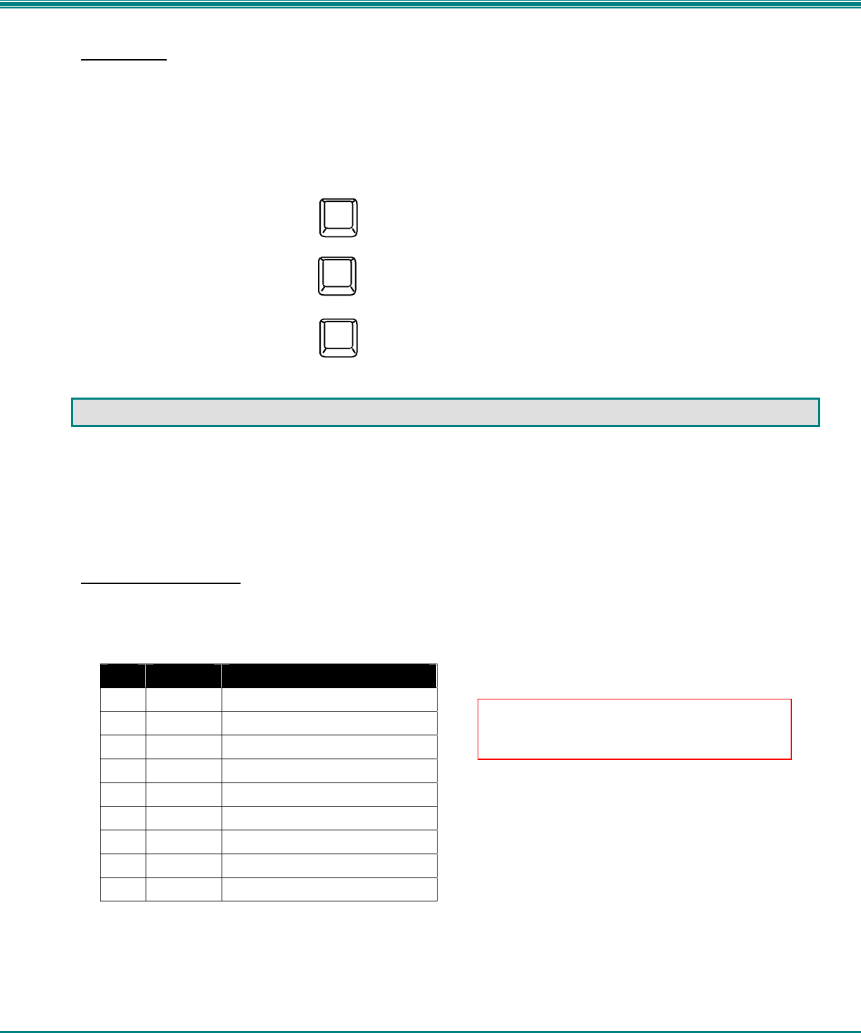
Function: Keystroke:
View the previous page of help
if available
View the next page of help
if available
Exit HELP and return to previous
mode
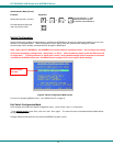
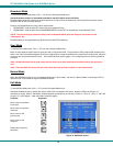
RS232 CONTROL
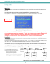
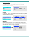
The NODEMUX can be configured to be controlled by a remote terminal connected through the RS232 port at the rear of the
NODEMUX. For RS232 communication with a remote terminal to work, the NODEMUX must first be configured for the baud rate
and address.
RS232 Connections and Configuration
Remote Connection
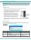
The RS232 Interface is designed to meet the RS232C standard and can be controlled from any CPU or other controller with an
RS232 communications port. The pin-out for the DB-9 connector on the unit is as follows:
RS232 Connector (DB-9 FEMALE)
PIN SIGNAL FUNCTION
1 CD Carrier Detect
2 TXD Transmit data (RXD at host)
3 RXD Receive data (TXD at host)
4 DTR Data terminal ready
5 GND Signal ground
6 DSR Data set ready
7 RTS Request to send
8 CTS Clear to send
9 - No connection
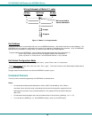
On the DB-9 female connector, pins 1 (DCD), 4 (DTR), and 6 (DSR) are shorted and pins 7 (RTS) and 8 (CTS) are shorted.
Therefore, host handshaking is bypassed and TXD and RXD are the only active signals. A straight through DB-9 cable (not null
modem) will work for most CPUs. To daisy chain multiple units, a Matrix Y-1 cable is used (see page 17) for each NODEMUX in
the chain.
Esc
Page
Down
Page
Up
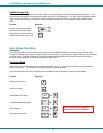
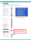
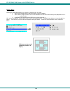
Note: Security must be disabled or user access
granted on the port(s) to be selected by RS-232
control.