


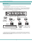

NTI AUDIO/HD VIDEO MATRIX SWITCH
7
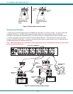
CONTROL OPTIONS
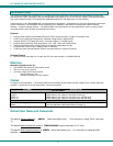
The VEEMUX-A video matrix switch has four methods of control:
• Front Panel LCD with Keypad
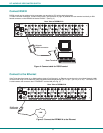
• Directly via an RS232 Interface
• Remotely via Ethernet (web interface)
• Infrared Remote (optional).
Every unit comes standard with the Front Panel LCD with Keypad, RS232, and Ethernet connection built-in. If desired, the
Infrared option must be requested at the time of the order. The Infrared option requires the purchase of a separate remote control
device (Infrared transmitter) as well as an Infrared receiver to be installed in the VEEMUX-A. No software is involved (see
Infrared Control on page 25). With the RS232 option, there are no external devices to be purchased. NTI provides software
commands as well as a test program to ensure the RS232 functions properly (see page 10 – RS232 Control).
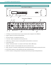
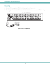
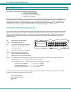
Front Panel LCD with Keypad Control
The front panel LCD and keypad allow the user to monitor switch status and route any display to any video source on the switch.
When the unit is powered up, each monitor is automatically connected to the video source of its equal number (i.e. monitor 1 to
source 1, monitor 2 to source 2, monitor 3 to source 3, etc.). Along with the routing of the inputs (video sources) to the outputs
(monitors) the keypad and LCD allow the users to configure the RS-232 control interface. The keypad buttons perform the
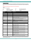
following functions.
ESC Escape back to the main display.
0 – 9 Used to enter numbers. ( # )
OUT The output user number can be entered
(2 digits or 1 digit and ENTER or IN)
followed by the input
IN Used following single digit output entries
ENTER Used following single digit entries
Display next 4 outputs and their inputs
Display previous 4 outputs and their inputs
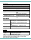
MENU The RS-232 menu is displayed. This allows the baud rate to be set at 9600, 2400, 1200 or 300 baud and the unit
address to be set to 1 - 15. See RS-232 control later in this chapter.
* Activate Memory Function - 10 memory locations 0 – 9, 0 is the power on default.
to Save current connections ( * ) ( OUT ) ( # ) ( ENTER )
to Recall connections from ( * ) ( IN ) ( # ) ( ENTER )
To set all outputs to one input ( * ) + ( # ) + (ENTER)
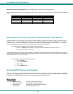
The following examples show various method of routing output 3 to input 5. Inputs and Outputs can be entered as a two digit
number or a one digit number followed by IN or ENTER.
(OUT) 3 (IN) 5 (ENTER)
(OUT) 3 (ENTER) 5 (ENTER
(OUT) 03 05
03 05
1 2 3
IN
4
5
6
OUT
7890
*
ESC
ENTER
MENU
V
IN: 1 2 3 4
OUT: 1 2 3 4
LCD WILL CYCLE TO DISPLAY A "v" FOR ALL VIDEO INPUTS FIRST, THEN A "a" FOR ALL AUDIO INPUTS.