


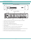

NTI AUDIO/HD VIDEO MATRIX SWITCH
10
RS232 Control
Remote Connection
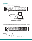
The RS232 Interface is designed to control the switch via serial (RS232) daisy chain connection from any host computer or other
controller with an RS232 communications port. There is, however, a restriction that must be followed:
A program must be used that will send an entire command line all at once, not character by character. (The
HyperTerminal program in WINDOWS cannot be used, as it sends each character one at a time.)
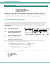
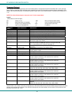
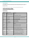
The pin outs for the DB-9 connector on the unit are as follows:
RS232 Connector (DB-9 FEMALE)
PIN SIGNAL FUNCTION
1
None no connection
2 TXD Transmit Data (RXD at host)
3 RXD Receive Data (TXD at host)
4 DSR Data Set Ready
5 GND Signal Ground
6 DTR Data Terminal Ready
7 CTS Clear to Send
8 RTS Request to Send
9
none no connection
On the DB-9 female connector, pins 4 (DSR) and 6 (DTR) are shorted and pins 7 (CTS) and 8 (RTS) are shorted. Therefore, host
handshaking is bypassed and TXD and RXD are the only active signals. A straight through DB-9 cable (not null modem) will work
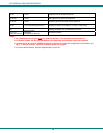
for most CPUs. To daisy chain multiple units, use NTI Matrix-Y-1 "Y" cables, except for the last unit connected. (see Fig 6). For a
pinout of the Matrix-Y-1 cable, see page 31. For straight through cable pinouts applicable to various terminal types, see page
30.
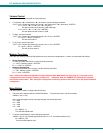
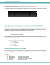
Baud Rate
The unit powers up with a default baud rate of 9600 and a fixed data protocol of 8 data bits, no parity and 1 stop bit. The baud
rate can be changed by pressing the MENU button on the front panel keypad. Then select 1 for SET BAUD RATE and select the
desired baud rate of 9600, 2400, 1200 or 300. A data protocol of 8 data bits, no parity, and 1 stop bit is used for communications.
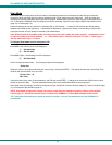
Unit Address
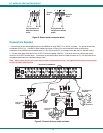
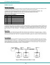
To allow multiple units to be controlled from a single CPU port, the RS232 control interface is designed to allow "daisy chaining"
up to 15 units using the NTI Matrix-Y-1 "Y" cables (sold separately- pin out is on page 28). By setting the appropriate unit address
with the keypad, each unit can be given a unique address (1-15). Then the unit will only respond to commands on the bus if its
address is embedded in the command. To set the unit address select MENU on the front panel keypad. Then select 2 for SET
UNIT ADDRESS and then type the address number (1-15) and (ENTER).
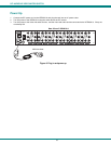
Figure 7- RS232 connection with Matrix-Y-1 cable
NTI
SWITCH
CPU
RS232
First Unit
NTI
SWITCH
RS232
NTI
SWITCH
RS232
Second Unit
Last Unit
RS232
Serial Port
Matrix-Y-1
Matrix-Y-1 Matrix-Y-1