


NTI UNIMUX SINGLE-USER HIGH DENSITY VGA USB KVM SWITCH
33
RS232 Command Protocol
Host controller commands supported by the unit are defined below.
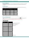
RS232 Command Protocol Quick Reference
Legend: (All numbers must be two digits)
SW : Switch (01-15) IP : Input Port/CPU (01-MAXINPUTS)
BR : Baud Rate Code <CR>: Carriage Return (Hex 0xD)
OP : Output/User Port (01-MAXOUTPUTS)
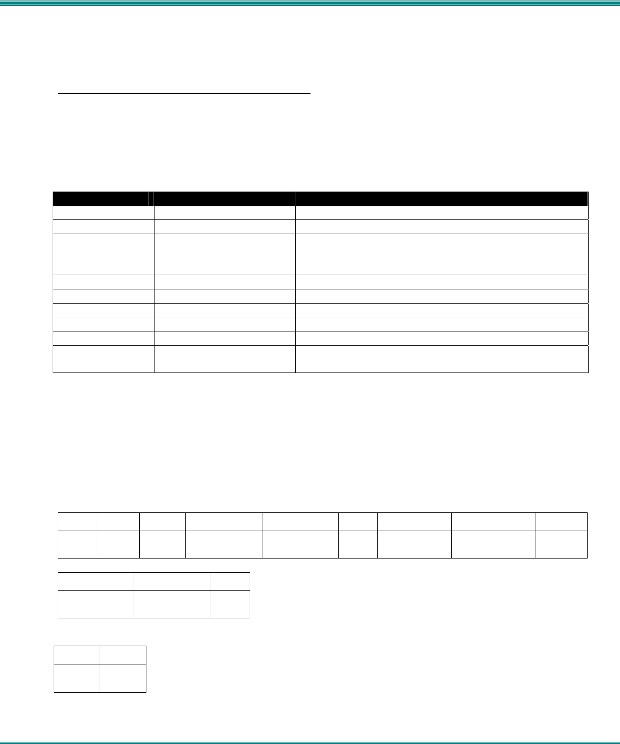
Command String Good Response Description
CS SW,IP,OP *<CR> Connect one User port To CPU port
RO SW,OP *<CR>IP<CR> Read Connection For User Port
CB 00,BR None Change Baud Rate For All Switches
BR = 12 (1200), 24 (2400), 48 (4800), 96 (9600), 19 (19200),
38 (38400), 57 (57600), 11(115000) (9600 is the default)
RV SW,00 *<CR>string\0<CR> Read NTI Version String
RU SW *<CR>IP,OP<CR> Read Unit Size
SS SW,00 *<CR> Disable Autostatus feature (see below)
SS SW,01 *<CR> Enable Autostatus feature (see below)
GO SW OP *<CR>go SW OP IP<CR> Report the User port that is connected to the CPU port
GM SW,00 *<CR>go SW OP IP<CR>
(all connections)
List all switch User port connections; all User ports to all CPU ports
If the first field is not a known command (as listed above) or SW field is different from the serial address programmed in the switch
memory, the command will be ignored. If the SW field corresponds to the serial address, but the syntax is wrong after this field,
the switch will answer with ?<CR>.
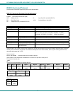
Syntax example:
CS 01,05,02<CR> (insert the space and commas as shown)
which means “At the switch with unit address 01, connect CPU port 05 to user port 02”
The switch will answer with:
∗<CR>
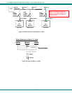
The HEX code representation of example above is:
Byte 1 Byte 2 Byte 3 Byte 4 Byte 5 Byte 6 Byte 7 Byte 8 Byte 9
‘C’
(0x43)
‘S’
(0x53)
Space
(0x20)
Switch – 1st digit
(0x30)
Switch – 2nd digit
(0x31)
‘,’
(0x2C)
Output – 1st digit
(0x30)
Output – 2nd digit
(0x35)
‘,’
(0x2C)
Byte 10 Byte 11 Byte 12
Input –1st digit
(0x30)
Input –2nd digit
(0x32)
<CR>
(0x0D)
Response:
Byte 1 Byte 2
‘∗’
(0x2A)
<CR>
(0x0D)