


INSTALLATION CONSIDERATIONS
Installing the TS-1 in New Construction (continued)
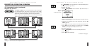
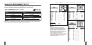
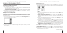
1. At a proposed site, install a New Construction Bracket to studs with nails or metal screws.
2. Use a cable tie to attach the CAT-5 cable(s) to the bracket at about 6" from the end(s) (see
Figure 14 on the previous page).
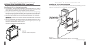
3. After drywall has been installed, use a drywall saw to cut out the opening (i.e., 4" h x 4.75" w)
for the TS-1.
4. Connect the CAT-5 cable(s) to the TS-1’s rear jack(s) (see Connecting the TS-1 on page 27).
IMPORTANT: Test cable prior to connection, miswired and damaged cables can cause dam-
age to the TS-1.
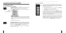
5. The TS-1 is equipped with two Mounting Clamps for easy installation. Hold the TS-1 firmly in
the opening and use a Phillips screwdriver to turn each mounting-clamp screw to the right
until the TS-1 feels fastened, as shown in Figure 13 on page 24.
NOTE: Do not overtighten the mounting-clamp screws.
I NTELLIP AD
®
Ci TOUCH S CREEN K EYPAD
26
I NTELLIP AD
®
Ci TOUCH S CREEN K EYPAD
27
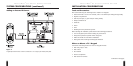
CONNECTING THE TS-1
Wiring Considerations
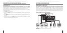
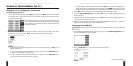
There are three distinct ways you can run CAT-5 cables between components in the system.
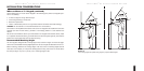
Attic/Basement Run
Drill a hole through the stud that caps the wall. Then run the cable from the attic or basement
and, using a fish tape, pull it up or down through the wall to the TS-1 opening.
Baseboard Run
Run the CAT-5 cable along or behind baseboards and then through the wall at the floor (below the
TS-1) and up to the opening.
Channel Drywall Run
Route out a shallow horizontal groove directly in the wallboard and lay the CAT-5 cable in the
channel. Then thread the cable behind the drywall between the studs to the TS-1. After the
installation is complete, patch the channels and any openings with a drywall compound.
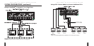
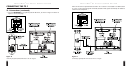
TS-1 Connections
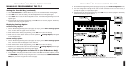
Each TS-1 has two CAT-5 jacks on its rear panel, as shown in Figure 2 on page 7.
• Using a CAT-5 cable, connect
SYSTEM
as a home run to the appropriate zone jack on the
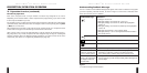
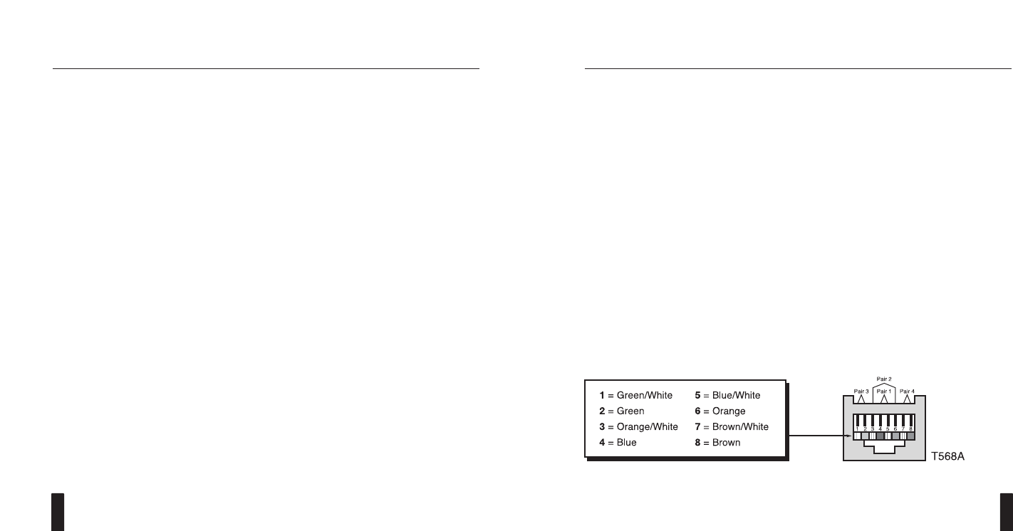
Niles Multi-Zone System. For wiring consistency, follow the color codes shown in Figure 15.
(Please refer to IMPORTANT warning on pages 24, 26).
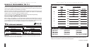
Figure 15
Color codes for RJ-45 connector.
continued on next page...