


22 Chapter 1 Describing the optical routing system
212257-B
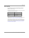
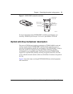
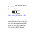
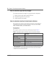
Figure 6 Four-channel CWDM OMUX front panel
Connectors with color-coded labels (Table 1) simplify connection to color-coded
CWDM GBICs in the switch.
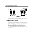
CWDM OMUX-4
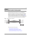
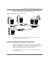
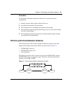
Figure 7 shows the CWDM OMUX-4 version, with four CWDM GBIC
equipment side connections.
Figure 7 CWDM OMUX-4 network and equipment side connections
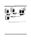
CWDM OMUX-8
Figure 8 shows the CWDM OMUX-8 version, with eight CWDM GBIC
equipment side connections.
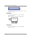
To Network
To Equipment side CWDM GBICs
RX
TX
RX TX RX TX RX TX RX TX
CWDM OMUX-4