


42 Chapter 3 Installing the shelf, OADM, and OMUX
212257-B
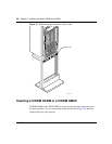
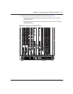
4 Make the following network backbone connections (Figure 17):
• Connect the network backbone east fiber optic cables to the east (left)
CWDM OMUX-4.
• Connect the network backbone west fiber optic cables to the west (right)
CWDM OMUX-4.
Cabling an eight-channel CWDM OMUX
This section describes how to cable the following:
• CWDM GBIC to a CWDM OMUX-8 (Figure 18)
• CWDM OMUX-8 to network backbone interfaces (Figure 18)
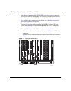
To connect a CWDM OMUX-8:
1 Install the CWDM GBICs (wavelength specific) into the network device(s).
To install a CWDM GBIC, see Installing CWDM Gigabit Interface
Converters, part number 212256-B.
2 Clean all fiber optic connectors on the cabling (see “Handling and cleaning
fiber optic equipment” on page 49).
3 Connect the fiber optic cables from the CWDM GBIC TX and RX connectors
to the CWDM OMUX-8 RX and TX connectors (Figure 18).
Note: The CWDM GBIC wavelength must match the CWDM OMUX-4
equipment connector wavelength.
The TX of one device must always connect to the RX of the next device.
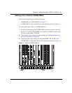
Note: The CWDM OMUX-8 located on the left side of the chassis
terminates the east network backbone connection. The CWDM OMUX-8
on the right side of the chassis terminates the west network backbone
connection. See Figure 18.
Note: The wavelength of the CWDM GBIC must match the wavelength
of the CWDM OMUX-8 equipment connector.