


Chapter 2 Calculating transmission distance 33
Installation and Networking Guidelines for Optical Routing
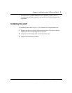
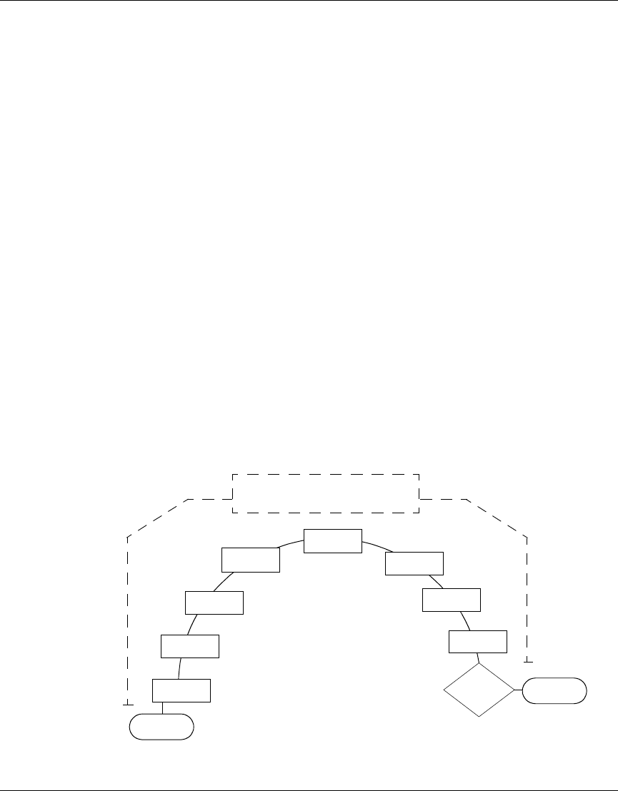
Hub and spoke transmission distance
Hub and Spoke topologies are the most complex. The characteristics of all
components designed into the network must be considered in calculating
transmission distance. The following factors determine maximum transmission
distance for the hub and spoke configuration in Figure 13:
• CWDM OADM insertion add loss
• CWDM OADM insertion drop loss
• Passthrough insertion loss for intermediate nodes
• Fiber attenuation of 0.25 per kilometer
The Ethernet switch host does not have to be near the CWDM OADM, and the
CWDM OADM does not regenerate signal. Therefore, maximum transmission
distance is from GBIC to GBIC.
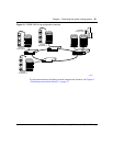
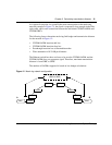
As the signal in Figure 13 passes from point A to point B (the most remote points
in the hub and spoke), it is expected to lose strength in the fiber optic cable, and in
each connection between the individual CWDM OADMs, the CWDM OMUX-8,
and the CWDM GBICs. The number of OADMs that can be supported is based on
the loss budget calculations.
Figure 13 Hub and spoke network configuration
OADM
OADM
A
B
OADM
OADM
OADM
OADM
OADM
GBIC
GBIC
OMUX-8
Transmission Distance
(GBIC to GBIC)
OADM