


45
Installation and Networking Guidelines for Optical Routing
Appendix A
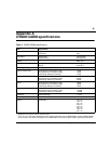
CWDM OADM specifications
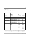
Table 9 CWDM OADM specifications
Item Specification
Physical Dimensions Plug-in Module Size
Rack Mount
8.35” x 1.7" x 10.4"
1RU
Connectors Network Side
Equipment Side
2 dual SC/PC
2 dual SC/PC
Cabling SMF, 9 µm
Environment Operating
Storage
0 to 60
0
C
40 to 85
0
C
Wavelength Usage Uni-directional
Typical insertion loss
*
*
Multiplexer loss values include connector loss.
TX Equipment to RX Network (add)
RX Equipment to TX Network (drop)
Passthrough (Network to Network)
1.2 dB
1.6 dB
1.5 dB
Maximum insertion loss
*
TX Equipment to RX Network (add)
RX Equipment to TX Network (drop)
Passthrough (Network to Network)
1.9 dB
2.3 dB
2.0 dB
Sigma TX Equipment to RX Network (add)
RX Equipment to TX Network (drop)
Passthrough (Network to Network)
.35 dB
.35 dB
.40 dB
Isolation TX Equipment to RX Network (add)
RX Equipment to TX Network (drop)
Passthrough (Network to Network)
> 25 dB
> 50 dB
> 28 dB
Passband Centerwavelength +/- 5nm
Directivity < 55 dB
Optical Wavelengths
†
†
There is a one nanometer offset between the stated wavelength for the CWDM GBICs and the CWDM OADMs
due to a shift in the center wavelength of the CWDM GBIC as it reaches typical system operating temperature.
1471 nm
1491 nm
1511 nm
1531 nm
1551 nm
1571 nm
1591 nm
1611 nm