


Chapter 1 Describing the optical routing system 23
Installation and Networking Guidelines for Optical Routing
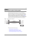
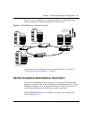
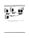
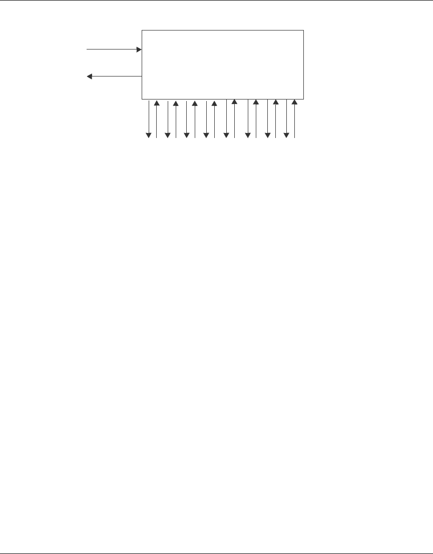
Figure 8 CWDM OMUX-8 network and equipment side connections
For information about installing a CWDM OMUX, see “Inserting a CWDM
OADM or a CWDM OMUX” on page 38. For specifications, see “CWDM
OMUX specifications” on page 47.
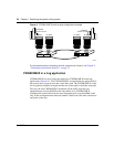
CWDM OMUX in a point-to-point application
Point-to-Point (PTP) optical networks carry data directly between two end points
without branching out to other points or nodes. PTP connections (Figure 9) are
made between mux/demuxs at each end. PTP connections transport many gigabits
of data from one location to another, such as linking two data centers to become
one virtual site, mirroring two sites for disaster recovery, or providing a large
amount of bandwidth between two buildings. The key advantage of a PTP
topology is the ability to deliver maximum bandwidth over a minimum amount of
fiber.
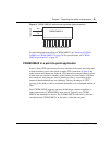
Each CWDM OMUX supports one network backbone connection and four or
eight connections to CWDM GBICs in the switch. Typically, two CWDM
OMUXs are installed in a chassis. The CWDM OMUX on the left is called the
east path and the CWDM OMUX on the right is called the west path.
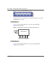
To Network
To Equipment side CWDM GBICs
RX
TX
RX TX
CWDM OMUX-8
RX TX RX TX RX TX RX TX RX TX RX TX RX TX