


Chapter 3 Installing the Passport 8250 device 33
Passport 8250 Installation Guide R2.2
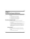
Connecting the ATM uplink port
1 Obtain the following equipment:
• Multi-mode fiberoptic cables withSC connectors with a typicalrange
of 0-2 km
• Single-mode fiber optic cables with SC connectors with a typical
range of 0-15 km
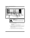
2 Connect the STM-1 or OC-3 single-mode or multi-mode fiber optic cable
to port A and port B located on the front panel of the Passport 8250
device.
The port A and port B are female SC connectors.
3 Connect the other end of the fiber optic cable to the far end.
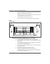
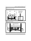
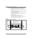
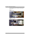
Connecting the dual power supply
See “Dual power supply” (page 34) for an illustration of the two power
supply modules.
WARNING
Network uplink cards A0768073 and A0760946 contain
class 1 laser and network uplink cards A0760934 and
A0780321 contain class 1 LED
Class 1 designated products are safe to view under normal
conditions. Output of the device is invisible to the human
eye. Avoid staring into the ends of fiber optical cables or
connectors.
For class 1 laser, the maximum output power is -8dBm and
the emission wavelength is 1310nm. For class 1 LED, the
maximum output power is -14dBm and the emission
wavelength is 1310nm.