


Chapter 3 Installing the Passport 8250 device 35
Passport 8250 Installation Guide R2.2
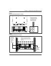
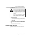
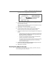
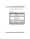
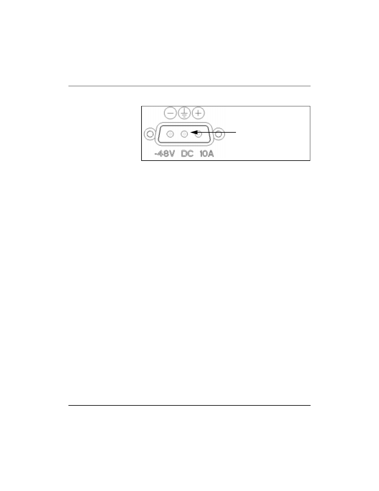
The central contact is designated as the chassis ground.
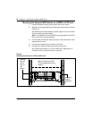
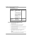
4 Connect the -48v power supply cable with the male 3W3-D connector to
the female 3W3-D connector.
Tighten the screws on the 3W3-Dconnector and verify that the connector
is secured to chassis of power supply.
5 Repeat steps 1 to 4 for the other power supply module.
6 Connect the power supply modules with the recommended wiring
harness to the branch circuit of the power distribution system.
7 Configure the electrical branch circuit providing power to the Passport as
follows:
• A double-pole disconnect switch which isolates both the power feed
and return conductors. A separate switch shall be provided for each
separate power feed to the equipment.
• The branch circuit protection shall be located in the ungrounded
conductor and be rated at no larger than 30A.
• The equipment protective grounding conductor shallbe permanently
connected to the protective earthing conductor in the building
electrical distribution system.
8 Connect to the power unit with the recommended wiring harness to the
branch circuit of the power distribution system.
9 Apply branch circuit power.
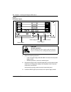
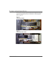
Securing the cables to the rack
Do not block air vents, field-replaceable modules, and LEDs with cables
when connecting the cables to the ports.
Centre contact of the
power input connector
is designated for the
product earth.