


48 Appendix A Replacing hardware
241-5101-200 R2.2
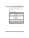
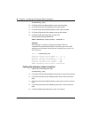
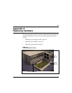
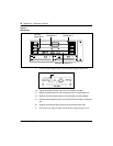
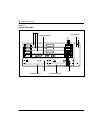
Figure 11
Board slots
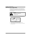
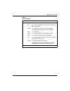
1 For each power supply module, set the power supply breaker to off.
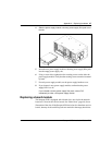
2 Flip the lock hatch at each end of the circuit board slot open.
3 Slide the network board or service board out of the circuit board slot.
4 Remove the new network board or service board from the package.
5 Insert thenew network board orservice boardinto the emptycircuit board
slot.
6 Snap the lock hatches at the ends of the circuit board slot close.
7
For each power supply module, set the power supply breakers to on.
Service
board slot 2
Service
board slot 3
Service
board slot 1
Network board slot 0
Breaker is off