


Chapter 2 Cabling the VPN Router and turning the power on 41
Nortel VPN Router Installation — VPN Router 600
Single V.35/X.21 WAN interface card LEDs
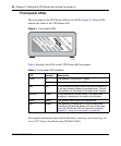
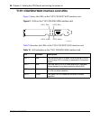
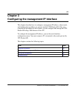
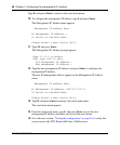
Figure 10 shows the LEDs on the single V.35/X.21 WAN interface card.
Figure 10 LEDs on the single V.35/X.21 WAN interface card
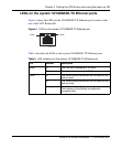
Table 11 describes the LEDs on the single V.35/X.21 WAN interface card.
Table 11 LED indicators on the single V.35/X.21 WAN interface card
LED Indicator Description
LED 1 Red No external transmit clock source is available.
LED 2 Green The signals CDC and DSR are on between the DSU
and the adapter. LED 2 detects receive link status.
LED 3 Green Power to the adapter is on and the onboard
microcode is loaded.
LED 4 Green Cable is detected.
LED 4, Green LED 3, Green
LED 1, Red LED 2, Green