


Appendix A Technical specifications 89
Nortel VPN Router Installation — VPN Router 600
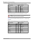
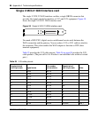
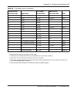
The following notes apply to the single X.21 cable:
1. Wires of pair 4 connect to wires of pair 5, but not to any pins in the DA-15.
2. The term “no conn” means the wire is not connected to a pin in the 15-pin connector.
3. Wires 13B and 14B connect to pin 8 in the 15-pin connector.
4. At each end, the cable shield and connector shell must connect to pin 1 of the connector.
5. Do not interconnect Shield to Signal Ground because these are separate signals.
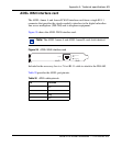
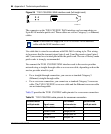
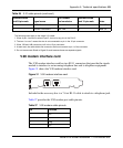
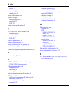
V.90 modem interface card
The V.90 modem interface card has two RJ-11 connectors that provide the signals
needed to interface to an incoming telephone line and to telephone equipment.
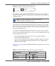
Figure 31 shows the V.90 modem interface card.
Figure 31 V.90 modem interface card
Included in the accessory box is a 7-foot RJ-11 cable to attach to a telephone jack.
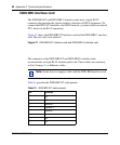
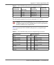
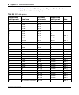
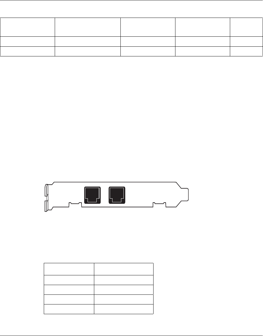
Table 27 provides the V.90 modem port cable pinouts.
1 SHIELD pair 14A 1 Note 4,5
7 SIGNAL GROUND pair 14B 8 Note 3,5
Table 27 V.90 modem cable pinouts
Pin Function
1N/C
2Tip
3 Ring
4N/C
Table 26 X.21 cable pinouts (continued)
Standard-wired
end 28-pin male Signal name
Pair number
and conductor
Standard-wired
end 15-pin male Notes
PHONE
LINE