


(Revised 2010-9-27) Page 13 of 159
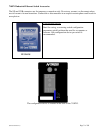
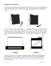
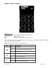
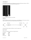
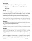
FRONT PANEL (710FX2)
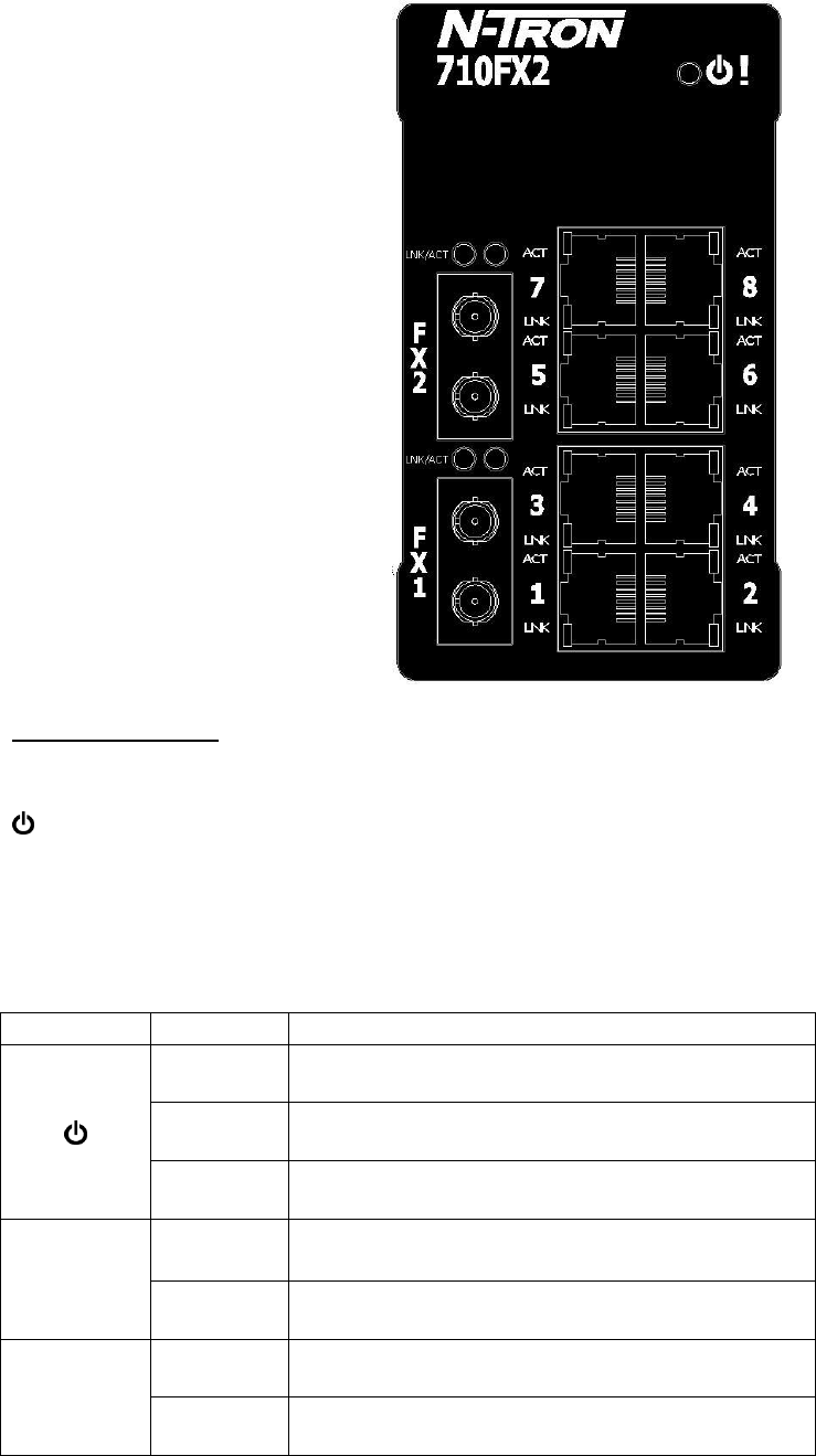
From Top to Left:
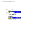
RJ45 Ports Auto Sensing 10/100 Base-TX Connections
Fiber Ports 100 Base-FX Connections
LED lights when Power is supplied to the unit
NOTE: The RJ45 data port has two LEDs located on each connector. The left LED indicates LINK status,
and the right LED indicates ACTIVITY.
LEDs: The table below describes the operating modes:
LED
Color
Description
GREEN
Power is ON
RED
Power is ON and a fault condition exists
OFF
Power is OFF
LNK
GREEN
10/100Mb Link between ports
OFF
No Link between ports
ACT
GREEN
Data is active between ports
OFF
Data is inactive between ports